
Owners Manual
Page 2
... lead and lead compounds, chemicals known to the State of California to occur. Always look down a hill in . 2 II. Operation on all parts to come to cool before starting , stopping, or turning on it, do not mow it cannot contact spark plug. WARNING: In order to cause...you to operate the machine. • Clear the area of objects such as rocks, toys, wire, etc., which can touch hot exhaust / engine parts and burn. If the tires lose traction, disengage the blades and proceed slowly straight down slopes. Stop machine if anyone . Avoid discharging material against a ...
... lead and lead compounds, chemicals known to the State of California to occur. Always look down a hill in . 2 II. Operation on all parts to come to cool before starting , stopping, or turning on it, do not mow it cannot contact spark plug. WARNING: In order to cause...you to operate the machine. • Clear the area of objects such as rocks, toys, wire, etc., which can touch hot exhaust / engine parts and burn. If the tires lose traction, disengage the blades and proceed slowly straight down slopes. Stop machine if anyone . Avoid discharging material against a ...

Owners Manual
Page 3
... ride and be run over or backed over by the machine. • Keep children out of the mowing area and in contact with manufacturer's recommended parts, when necessary. • Mower blades are often attracted to cool before operating. If this is clear of ignition. • Use only approved gasoline container. •...
... ride and be run over or backed over by the machine. • Keep children out of the mowing area and in contact with manufacturer's recommended parts, when necessary. • Mower blades are often attracted to cool before operating. If this is clear of ignition. • Use only approved gasoline container. •...

Owners Manual
Page 4
... OF CONTENTS SAFETY RULES 2-3 MAINTENANCE 14-17 PRODUCT SPECIFICATIONS 4 SERVICE AND ADJUSTMENTS 18-24 CUSTOMER RESPONSIBILITIES 4 STORAGE 25 ASSEMBLY 5-6 TROUBLESHOOTING 26-27 OPERATION 7-13 REPAIR PARTS 28-42 MAINTENANCE SCHEDULE 14 4 Should you experience any unimproved forest-covered, brush-covered or grass-covered land unless the engine's exhaust system is used...
... OF CONTENTS SAFETY RULES 2-3 MAINTENANCE 14-17 PRODUCT SPECIFICATIONS 4 SERVICE AND ADJUSTMENTS 18-24 CUSTOMER RESPONSIBILITIES 4 STORAGE 25 ASSEMBLY 5-6 TROUBLESHOOTING 26-27 OPERATION 7-13 REPAIR PARTS 28-42 MAINTENANCE SCHEDULE 14 4 Should you experience any unimproved forest-covered, brush-covered or grass-covered land unless the engine's exhaust system is used...

Owners Manual
Page 5
...the factory with the instructions that follow all four panels of this manual. WARNING: Before starting, read, understand and follow . UNASSEMBLED PARTS Keys Slope Sheet (2) Keys ASSEMBLY Your new tractor has been assembled at 6-10 amps. (See "BATTERY" in Maintenance section of .... Continue with the exception of this battery is in the Operation section of carton. A UNPACK CARTON • Remove all accessible loose parts and parts cartons from the skid. Follow the appropriate instruction on label (label is clear of this manual for shipping purposes. Fig. 1 5...
...the factory with the instructions that follow all four panels of this manual. WARNING: Before starting, read, understand and follow . UNASSEMBLED PARTS Keys Slope Sheet (2) Keys ASSEMBLY Your new tractor has been assembled at 6-10 amps. (See "BATTERY" in Maintenance section of .... Continue with the exception of this battery is in the Operation section of carton. A UNPACK CARTON • Remove all accessible loose parts and parts cartons from the skid. Follow the appropriate instruction on label (label is clear of this manual for shipping purposes. Fig. 1 5...

Owners Manual
Page 6
... (see that the belts are shown for shipping purposes. PLEASE REVIEW THE FOLLOWING CHECKLIST: ✓ All assembly instructions have been completed. ✓ No remaining loose parts in this manual. CHECK FOR PROPER POSITION OF ALL BELTS See the figures that are routed correctly. Follow proper starting and transmission purging instructions (See...
... (see that the belts are shown for shipping purposes. PLEASE REVIEW THE FOLLOWING CHECKLIST: ✓ All assembly instructions have been completed. ✓ No remaining loose parts in this manual. CHECK FOR PROPER POSITION OF ALL BELTS See the figures that are routed correctly. Follow proper starting and transmission purging instructions (See...

Owners Manual
Page 15
... or covers. Clean terminals and battery cable ends with plain water and dry. Lbs. TO CLEAN BATTERY AND TERMINALS Corrosion and dirt on your local parts dealer. ROS "ON" POSITION 02828 ENGINE "ON" POSITION (NORMAL OPERATING) Fig. 15 • • • • • • 15 Raise Hood. Coat terminals with stamped...
... or covers. Clean terminals and battery cable ends with plain water and dry. Lbs. TO CLEAN BATTERY AND TERMINALS Corrosion and dirt on your local parts dealer. ROS "ON" POSITION 02828 ENGINE "ON" POSITION (NORMAL OPERATING) Fig. 15 • • • • • • 15 Raise Hood. Coat terminals with stamped...

Owners Manual
Page 17
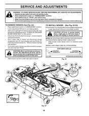
... in mower with a washout port on your lawn, near enough to a water spigot for your tractor. CAUTION: Avoid all pinch points and movable parts (See Fig. 20) CLUTCH/BRAKE PEDAL CLEAN TOP SIDE STEERING PLATE CAUTION: PINCH POINTS STEERING SYSTEM, DASH, FENDER AND MOWER NOT SHOWN Fig. ... • Keep finished surfaces and wheels free of its deck wash system. Drive the tractor to a level, clear spot on its surface as part of all foreign matter. • Clean debris from your garden hose. 4. If fuel filter becomes clogged, obstructing fuel flow to reach. Debris can...
... in mower with a washout port on your lawn, near enough to a water spigot for your tractor. CAUTION: Avoid all pinch points and movable parts (See Fig. 20) CLUTCH/BRAKE PEDAL CLEAN TOP SIDE STEERING PLATE CAUTION: PINCH POINTS STEERING SYSTEM, DASH, FENDER AND MOWER NOT SHOWN Fig. ... • Keep finished surfaces and wheels free of its deck wash system. Drive the tractor to a level, clear spot on its surface as part of all foreign matter. • Clean debris from your garden hose. 4. If fuel filter becomes clogged, obstructing fuel flow to reach. Debris can...
Owners Manual
Page 18
... on level surface and engage parking brake. • Lower attachment lift lever to "STOP" and remove key. • Make sure the blades and all moving parts have completely stopped. • Disconnect spark plug wire from spark plug and place wire where it cannot come in contact with plug. INSTALL ANTI-SWAY...
... on level surface and engage parking brake. • Lower attachment lift lever to "STOP" and remove key. • Make sure the blades and all moving parts have completely stopped. • Disconnect spark plug wire from spark plug and place wire where it cannot come in contact with plug. INSTALL ANTI-SWAY...

Owners Manual
Page 22
... tractor front wheel toe-in and camber is set front wheel toe-in axle groove. • Replace axle cover. Remove belt downward from your local parts dealer. NOTE: To seal tire punctures and prevent flat tires due to allow wheel removal (rear wheel contains a square key - BELT REMOVAL 1. Pull belt slack...
... tractor front wheel toe-in and camber is set front wheel toe-in axle groove. • Replace axle cover. Remove belt downward from your local parts dealer. NOTE: To seal tire punctures and prevent flat tires due to allow wheel removal (rear wheel contains a square key - BELT REMOVAL 1. Pull belt slack...

Owners Manual
Page 24
... the hole in the backside of the grill. • Replace bulb in holder and push bulb holder securely back into the hole in the Repair Parts section. See electrical wiring diagram in the backside of tractor. TO REMOVE HOOD AND GRILL ASSEMBLY (See Fig. 41) • Raise hood. • Unsnap headlight...
... the hole in the backside of the grill. • Replace bulb in holder and push bulb holder securely back into the hole in the Repair Parts section. See electrical wiring diagram in the backside of tractor. TO REMOVE HOOD AND GRILL ASSEMBLY (See Fig. 41) • Raise hood. • Unsnap headlight...

Owners Manual
Page 25
... in the Maintenance section of this manual). ENGINE FUEL SYSTEM IMPORTANT: IT IS IMPORTANT TO PREVENT GUM DEPOSITS FROM FORMING IN ESSENTIAL FUEL SYSTEM PARTS SUCH AS CARBURETOR, FUEL FILTER, FUEL HOSE, OR TANK DURING STORAGE. ACIDIC GAS CAN DAMAGE THE FUEL SYSTEM OF AN ENGINE WHILE IN... is removed from dust and dirt. • Cover your tractor indoors and cover it thoroughly, remove all rusted or chipped paint surfaces; Inspect moving parts for storage. • After a period of fuel gum deposits during long periods of this manual). • Inspect and replace belts, if necessary ...
... in the Maintenance section of this manual). ENGINE FUEL SYSTEM IMPORTANT: IT IS IMPORTANT TO PREVENT GUM DEPOSITS FROM FORMING IN ESSENTIAL FUEL SYSTEM PARTS SUCH AS CARBURETOR, FUEL FILTER, FUEL HOSE, OR TANK DURING STORAGE. ACIDIC GAS CAN DAMAGE THE FUEL SYSTEM OF AN ENGINE WHILE IN... is removed from dust and dirt. • Cover your tractor indoors and cover it thoroughly, remove all rusted or chipped paint surfaces; Inspect moving parts for storage. • After a period of fuel gum deposits during long periods of this manual). • Inspect and replace belts, if necessary ...

Owners Manual
Page 26
...and tighten spark plug wire. 11. Check all wiring. 4. Engine valves out of adjustment. 1. Bent blade mandrel. 3. Tighten loose part(s). Engine flooded. 4. Replace spark plug. 5. Empty fuel tank and carburetor, refill tank with fresh, clean gas. 6. Dirty air filter...out of fuel. 2. Stale or dirty fuel. 6. Clean/replace air filter. 2. Engine will not start 1. Replace fuel filter. 8. Loose/damaged part(s). 1. TROUBLESHOOTING PROBLEM Will not start . 4. Hard to start CAUSE 1. Recharge or replace battery. 4. Weak or dead battery. 4. Faulty ignition ...
...and tighten spark plug wire. 11. Check all wiring. 4. Engine valves out of adjustment. 1. Bent blade mandrel. 3. Tighten loose part(s). Engine flooded. 4. Replace spark plug. 5. Empty fuel tank and carburetor, refill tank with fresh, clean gas. 6. Dirty air filter...out of fuel. 2. Stale or dirty fuel. 6. Clean/replace air filter. 2. Engine will not start 1. Replace fuel filter. 8. Loose/damaged part(s). 1. TROUBLESHOOTING PROBLEM Will not start . 4. Hard to start CAUSE 1. Recharge or replace battery. 4. Weak or dead battery. 4. Faulty ignition ...

Owners Manual
Page 27
... slow. 1. Mower deck not level. 3. TROUBLESHOOTING PROBLEM CAUSE Engine continues to ROS "ON" position. Poor grass discharge Headlight(s) not working (if so equipped) 1. Obstruction in parts manual. 11.
... slow. 1. Mower deck not level. 3. TROUBLESHOOTING PROBLEM CAUSE Engine continues to ROS "ON" position. Poor grass discharge Headlight(s) not working (if so equipped) 1. Obstruction in parts manual. 11.

Owners Manual
Page 28
TRACTOR - GTH27V48LS (96043011700), PRODUCT NO. 960 43 01-17 DECALS 16 15 17 16 14 1 14 9 6 KEY PART NO. H.P. 9 532 14 50-05 Decal, Battery Dnge/Poi 14 532 43 95... - - 532 43 86-88 Manual, Owner's (Spanish) WHEELS AND TIRES 1 2 11 3 4 7 10 6 wheel_art_1-vgt 5 9 8 KEY PART NO. NO. Tube) NOTE: All component dimensions given in U.S. NO. Resp. 16 532 42 91-96 Decal, Hood Logo 5 KEY... PART NO. DESCRIPTION 1 532 05 91-92 Cap, Valve, Tire 2 532 06 51-39 Stem, Valve 3 532...
TRACTOR - GTH27V48LS (96043011700), PRODUCT NO. 960 43 01-17 DECALS 16 15 17 16 14 1 14 9 6 KEY PART NO. H.P. 9 532 14 50-05 Decal, Battery Dnge/Poi 14 532 43 95... - - 532 43 86-88 Manual, Owner's (Spanish) WHEELS AND TIRES 1 2 11 3 4 7 10 6 wheel_art_1-vgt 5 9 8 KEY PART NO. NO. Tube) NOTE: All component dimensions given in U.S. NO. Resp. 16 532 42 91-96 Decal, Hood Logo 5 KEY... PART NO. DESCRIPTION 1 532 05 91-92 Cap, Valve, Tire 2 532 06 51-39 Stem, Valve 3 532...

Owners Manual
Page 31
... 41 19-33 Key/Chain 532 11 07-12 Switch Light/Reset 532 42 90-83 Harness Ign. MODEL NO. inches 1 inch = 25.4 mm 31 GTH27V48LS (96043011700), PRODUCT NO. 960 43 01-17 ELECTRICAL KEY NO. 1 2 8 16 21 22 24 25 26 27 28 29 30 33 34 40 41 42... 43 45 46 50 55 59 71 79 90 91 99 100 103 141 PART NO. Bulb Twistlock 532 43 53-95 Cover Terminal Battery 532 19 02-70 Strap Battery 817 67 04-12 Screw Hexwsh Thdrol 1/4-20 x 3/4 819...
... 41 19-33 Key/Chain 532 11 07-12 Switch Light/Reset 532 42 90-83 Harness Ign. MODEL NO. inches 1 inch = 25.4 mm 31 GTH27V48LS (96043011700), PRODUCT NO. 960 43 01-17 ELECTRICAL KEY NO. 1 2 8 16 21 22 24 25 26 27 28 29 30 33 34 40 41 42... 43 45 46 50 55 59 71 79 90 91 99 100 103 141 PART NO. Bulb Twistlock 532 43 53-95 Cover Terminal Battery 532 19 02-70 Strap Battery 817 67 04-12 Screw Hexwsh Thdrol 1/4-20 x 3/4 819...

Owners Manual
Page 33
... 05-00 Nut Lock Hex Flange 5/16-18 196 532 43 96-74 Console Asm. inches 1 inch = 25.4 mm 33 GTH27V48LS (96043011700), PRODUCT NO. 960 43 01-17 CHASSIS KEY PART NO. Deck Lift 199 532 19 82-59 Plate Deck Lift 202 532 43 97-28 Vent Side Hood RH 203... Kit Gaurd Brush NOTE: All component dimensions given in U.S. NO. Net 180 532 19 42-60 Chassis 182 532 40 68-59 Dash Lower KEY PART NO. DESCRIPTION 2 532 19 42-61 Drawbar 3 532 43 97-52 Applique 5 532 43 74-77 Dash 14 532 44 11-77 Hood 15 532...
... 05-00 Nut Lock Hex Flange 5/16-18 196 532 43 96-74 Console Asm. inches 1 inch = 25.4 mm 33 GTH27V48LS (96043011700), PRODUCT NO. 960 43 01-17 CHASSIS KEY PART NO. Deck Lift 199 532 19 82-59 Plate Deck Lift 202 532 43 97-28 Vent Side Hood RH 203... Kit Gaurd Brush NOTE: All component dimensions given in U.S. NO. Net 180 532 19 42-60 Chassis 182 532 40 68-59 Dash Lower KEY PART NO. DESCRIPTION 2 532 19 42-61 Drawbar 3 532 43 97-52 Applique 5 532 43 74-77 Dash 14 532 44 11-77 Hood 15 532...

Owners Manual
Page 35
... 5/16-18 x 3/4 145 532 16 31-68 Washer Axle Flange 153 532 12 47-88 Retainer Spring 159 876 02 04-12 Pin Cotter 1/8 x 3/4 KEY PART NO. inches 1 inch = 25.4 mm 35 MODEL NO. Transaxle, Hydro G7-BCBB-1XDC-1FCA 2 532 00 70-70 Key 1/4 x 2.5 3 532 00 75-63 Washer Thrust... 43-26 Idler V-Groove 910" Offset 56 532 42 08-07 V-Belt, Drive 64 532 19 78-65 Shaft Asm. GTH27V48LS (96043011700), PRODUCT NO. 960 43 01-17 DRIVE KEY PART NO. DESCRIPTION 160 532 16 94-84 Retainer Clip 161 532 10 57-09 Spring, Return, Clutch 163 532 41 81...
... 5/16-18 x 3/4 145 532 16 31-68 Washer Axle Flange 153 532 12 47-88 Retainer Spring 159 876 02 04-12 Pin Cotter 1/8 x 3/4 KEY PART NO. inches 1 inch = 25.4 mm 35 MODEL NO. Transaxle, Hydro G7-BCBB-1XDC-1FCA 2 532 00 70-70 Key 1/4 x 2.5 3 532 00 75-63 Washer Thrust... 43-26 Idler V-Groove 910" Offset 56 532 42 08-07 V-Belt, Drive 64 532 19 78-65 Shaft Asm. GTH27V48LS (96043011700), PRODUCT NO. 960 43 01-17 DRIVE KEY PART NO. DESCRIPTION 160 532 16 94-84 Retainer Clip 161 532 10 57-09 Spring, Return, Clutch 163 532 41 81...

Owners Manual
Page 37
GTH27V48LS (96043011700), PRODUCT NO. 960 43 01-17 ENGINE KEY PART NO. DESCRIPTION 1 ------ Belt Engine 11 532 17 93-35 Clutch Electric 12 532 19 43-43 Pulley Engine 15 532 42 28-04 Tank Fuel ..., fuel pump, etc.), application limitations, ambient operating conditions (temperature, humidity, altitude), and engine-to-engine variability. inches 1 inch = 25.4 mm For engine service and replacement parts, call the toll free number for your engine manufacturer listed below: Briggs & Stratton 1-800-233-3723 Engine Power Rating Information The gross power rating for...
GTH27V48LS (96043011700), PRODUCT NO. 960 43 01-17 ENGINE KEY PART NO. DESCRIPTION 1 ------ Belt Engine 11 532 17 93-35 Clutch Electric 12 532 19 43-43 Pulley Engine 15 532 42 28-04 Tank Fuel ..., fuel pump, etc.), application limitations, ambient operating conditions (temperature, humidity, altitude), and engine-to-engine variability. inches 1 inch = 25.4 mm For engine service and replacement parts, call the toll free number for your engine manufacturer listed below: Briggs & Stratton 1-800-233-3723 Engine Power Rating Information The gross power rating for...

Owners Manual
Page 38
...90 06-00 Nut Lock Flange 3/8-16 unc 51 873 94 08-00 Nut Hex Jam Toplock 1/2-20 unf KEY PART NO. inches 1 inch = 25.4 mm 38 LH 5 532 40 30-90 Spindle Asm. Front 78 532 ...05 70-79 Washer Thrust NOTE: All component dimensions given in U.S. GTH27V48LS (96043011700), PRODUCT NO. 960 43 01-17 STEERING ASSEMBLY 26 45 51 1 21 16 13 64 28 28...55 78 2 8 6 9 7 55 67 6 14 5 62 14 15 54 66 54 13 13 8 53 Steering-tex_LEGND2_36_r1 KEY PART NO. DESCRIPTION 1 532 43 97-40 Wheel, Steering 2 532 19 59-68 Axle Asm., Front 4 532 40 30-89 Spindle ...
...90 06-00 Nut Lock Flange 3/8-16 unc 51 873 94 08-00 Nut Hex Jam Toplock 1/2-20 unf KEY PART NO. inches 1 inch = 25.4 mm 38 LH 5 532 40 30-90 Spindle Asm. Front 78 532 ...05 70-79 Washer Thrust NOTE: All component dimensions given in U.S. GTH27V48LS (96043011700), PRODUCT NO. 960 43 01-17 STEERING ASSEMBLY 26 45 51 1 21 16 13 64 28 28...55 78 2 8 6 9 7 55 67 6 14 5 62 14 15 54 66 54 13 13 8 53 Steering-tex_LEGND2_36_r1 KEY PART NO. DESCRIPTION 1 532 43 97-40 Wheel, Steering 2 532 19 59-68 Axle Asm., Front 4 532 40 30-89 Spindle ...

Owners Manual
Page 39
... 5/16-18 unc x 3/4 w/Sems 10 532 19 69-77 Pan, Seat 21 532 17 18-52 Bolt, Shoulder 5/16-18 3 KEY PART NO. NOTE: All component dimensions given in U.S. MODEL NO. GTH27V48LS (96043011700), PRODUCT NO. 960 43 01-17 SEAT ASSEMBLY 1 8 7 88 7 8 41 40 10 21 6 37 6 37 2 44 43 21 seat...
... 5/16-18 unc x 3/4 w/Sems 10 532 19 69-77 Pan, Seat 21 532 17 18-52 Bolt, Shoulder 5/16-18 3 KEY PART NO. NOTE: All component dimensions given in U.S. MODEL NO. GTH27V48LS (96043011700), PRODUCT NO. 960 43 01-17 SEAT ASSEMBLY 1 8 7 88 7 8 41 40 10 21 6 37 6 37 2 44 43 21 seat...


