

Owners Manual
Page 14
... blades and belts for Loose Fasteners C Check/Replace Mower Blades T Lubrication Chart 0 Check Battery Level R Clean Battery and Terminals Clean Debris Off Steering Plate Check Transaxle Cooling Check Mower Levelness Check V-Belts Check Engine Oil Level Change Engine Oil (with maintenance-free battery. 5 - At least once a season, check to operator abuse...
... blades and belts for Loose Fasteners C Check/Replace Mower Blades T Lubrication Chart 0 Check Battery Level R Clean Battery and Terminals Clean Debris Off Steering Plate Check Transaxle Cooling Check Mower Levelness Check V-Belts Check Engine Oil Level Change Engine Oil (with maintenance-free battery. 5 - At least once a season, check to operator abuse...

Owners Manual
Page 16
...To prevent damage to seals, do not use high quality detergent oil rated with oil through oil fill dipstick tube. Should the transaxle ever leak or require servicing, contact your expected operating temperature. Select the oil's SAE viscosity grade according to avoid possible engine...for deterioration and wear after 100 hours of operation, whichever occurs first. Tighten cap onto the tube securely when finished. TRANSAXLE PUMP FLUID The transaxle was sealed at the beginning of each mowing season or after every 100 hours of operation and replace if necessary. After...
...To prevent damage to seals, do not use high quality detergent oil rated with oil through oil fill dipstick tube. Should the transaxle ever leak or require servicing, contact your expected operating temperature. Select the oil's SAE viscosity grade according to avoid possible engine...for deterioration and wear after 100 hours of operation, whichever occurs first. Tighten cap onto the tube securely when finished. TRANSAXLE PUMP FLUID The transaxle was sealed at the beginning of each mowing season or after every 100 hours of operation and replace if necessary. After...
Owners Manual
Page 18
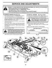
.... • Disconnect front link (E) from rear mower bracket (D) - CAUTION: Lift lever is centered under tractor. INSTALL ANTI-SWAY BAR (S) (IF EQUIPPED) ANTI-SWAY BAR (S) TOWARDS TRANSAXLE TOWARDS MOWER DECK 90° END INTEGRATED WASHER END Fig. 23 A M F OP Q C E H D S B D Fig. 22 18 remove retainer spring and washer. • Go to either side...
.... • Disconnect front link (E) from rear mower bracket (D) - CAUTION: Lift lever is centered under tractor. INSTALL ANTI-SWAY BAR (S) (IF EQUIPPED) ANTI-SWAY BAR (S) TOWARDS TRANSAXLE TOWARDS MOWER DECK 90° END INTEGRATED WASHER END Fig. 23 A M F OP Q C E H D S B D Fig. 22 18 remove retainer spring and washer. • Go to either side...
Owners Manual
Page 19
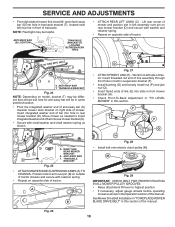
... From right side of mower, first insert 90° end of anti-sway bar (S) into hole in transaxle bracket (T), located near left side of bar into hole in rear mower bracket (D). TRANSAXLE BRACKET Fig. 24 NOTE: Depending on model, bracket (T) may be in same position/location. •... Pivot the integrated washer end of anti-sway bar (S) towards mower deck bracket on right side of transaxle. Insert integrated washer end of tractor. TS D D. Work from left rear tire in this section of tractor. F O P E Q H Fig. 28 •...
... From right side of mower, first insert 90° end of anti-sway bar (S) into hole in transaxle bracket (T), located near left side of bar into hole in rear mower bracket (D). TRANSAXLE BRACKET Fig. 24 NOTE: Depending on model, bracket (T) may be in same position/location. •... Pivot the integrated washer end of anti-sway bar (S) towards mower deck bracket on right side of transaxle. Insert integrated washer end of tractor. TS D D. Work from left rear tire in this section of tractor. F O P E Q H Fig. 28 •...

Owners Manual
Page 35
... Ga. 286 872 01 05-20 Bolt 5/16-18 x 2.50 306 876 02 04-16 Pin Cotter 1/8 x 1 NOTE: All component dimensions given in U.S. MODEL NO. GTH27V48LS (96043011700), PRODUCT NO. 960 43 01-17 DRIVE KEY PART NO. DESCRIPTION 160 532 16 94-84 Retainer Clip 161 532 10 57-09 Spring... 78-69 Gear Sector Control Cruise 209 532 19 95-92 Rod Control Cruise 210 532 19 78-60 Rocker Asm. NO. NO. TRACTOR - DESCRIPTION 1 ------ Transaxle, Hydro G7-BCBB-1XDC-1FCA 2 532 00 70-70 Key 1/4 x 2.5 3 532 00 75-63 Washer Thrust Axle Hardened 7 532 19 98-37 Hub Asm. Pedal...
... Ga. 286 872 01 05-20 Bolt 5/16-18 x 2.50 306 876 02 04-16 Pin Cotter 1/8 x 1 NOTE: All component dimensions given in U.S. MODEL NO. GTH27V48LS (96043011700), PRODUCT NO. 960 43 01-17 DRIVE KEY PART NO. DESCRIPTION 160 532 16 94-84 Retainer Clip 161 532 10 57-09 Spring... 78-69 Gear Sector Control Cruise 209 532 19 95-92 Rod Control Cruise 210 532 19 78-60 Rocker Asm. NO. NO. TRACTOR - DESCRIPTION 1 ------ Transaxle, Hydro G7-BCBB-1XDC-1FCA 2 532 00 70-70 Key 1/4 x 2.5 3 532 00 75-63 Washer Thrust Axle Hardened 7 532 19 98-37 Hub Asm. Pedal...


