Owner's Manual
Page 1
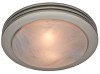
Installation Guide ENGLISH See page 2 Español Vea la página 21 90052/90053/90054/90058 Saturn™ Bath Ventilator with Light READ and SAVE THESE INSTRUCTIONS 028_41718_EngS_1.28.08_Arial.indd 1 1 41718-01 01/28/2008 1/28/08 10:47:06 AM
Installation Guide ENGLISH See page 2 Español Vea la página 21 90052/90053/90054/90058 Saturn™ Bath Ventilator with Light READ and SAVE THESE INSTRUCTIONS 028_41718_EngS_1.28.08_Arial.indd 1 1 41718-01 01/28/2008 1/28/08 10:47:06 AM
Owner's Manual
Page 2
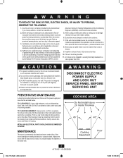
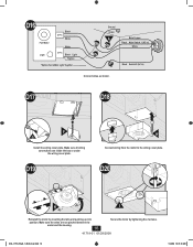
... spray, construction dust, etc. off at service panel and lock the service disconnecting means to tab) and twist screwdriver. DO NOT install this unit is designed for the application and be done by the manufacturer. This product is to prevent backdrafting. Disconnect the power supply... MAINTENANCE The motor is needed for Heating, Refrigeration and Air-Conditioning Engineers (ASHRAE), and the local code authorities. 2. COOKING AREA Do Not Install Above Or Inside This Area 45° 45° Cooking Equipment Floor 2 41718-01 01/28/2008 028_41718_EngS_1.28.08_Arial.indd 2 1/28/...
... spray, construction dust, etc. off at service panel and lock the service disconnecting means to tab) and twist screwdriver. DO NOT install this unit is designed for the application and be done by the manufacturer. This product is to prevent backdrafting. Disconnect the power supply... MAINTENANCE The motor is needed for Heating, Refrigeration and Air-Conditioning Engineers (ASHRAE), and the local code authorities. 2. COOKING AREA Do Not Install Above Or Inside This Area 45° 45° Cooking Equipment Floor 2 41718-01 01/28/2008 028_41718_EngS_1.28.08_Arial.indd 2 1/28/...
Owner's Manual
Page 3
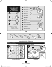
...-01-000 E 95029-01-000 F 75191-01-000 G 03242-07-133 H 95491-01-000 x2 I Extra Screws * NOTE: Strain relief cable connector must be installed. Before Installation 1 Tools Needed. (Not supplied) Estimated assembly time: 30 to 60 minutes NOTE: Remove all the parts. Check all packing materials before... installation. 2 I E Turn off the power source. 028_41718_EngS_1.28.08_Arial.indd 3 3 41718-01 01/28/2008 Loosen screws. 1/28/08 10:47:09 AM Not ...
...-01-000 E 95029-01-000 F 75191-01-000 G 03242-07-133 H 95491-01-000 x2 I Extra Screws * NOTE: Strain relief cable connector must be installed. Before Installation 1 Tools Needed. (Not supplied) Estimated assembly time: 30 to 60 minutes NOTE: Remove all the parts. Check all packing materials before... installation. 2 I E Turn off the power source. 028_41718_EngS_1.28.08_Arial.indd 3 3 41718-01 01/28/2008 Loosen screws. 1/28/08 10:47:09 AM Not ...
Owner's Manual
Page 5
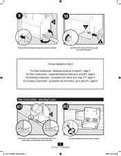
Choose Installation Option For New Construction - B Insert the strain relief into joist or framing. 5 41718-01 01/28/2008 028_41718_EngS_1.28.08_Arial.indd 5 1/28/08 10:47:...
Choose Installation Option For New Construction - B Insert the strain relief into joist or framing. 5 41718-01 01/28/2008 028_41718_EngS_1.28.08_Arial.indd 5 1/28/08 10:47:...
Owner's Manual
Page 6
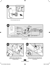
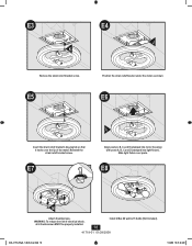
... *Option Fan & Main Light Together Ground Green A Bare Copper Black Main Switch 1 (AC In) White Black Switch 2 (AC In) Connect wires as shown. A15 A016 E G Install the wiring cover plate.
... *Option Fan & Main Light Together Ground Green A Bare Copper Black Main Switch 1 (AC In) White Black Switch 2 (AC In) Connect wires as shown. A15 A016 E G Install the wiring cover plate.
Owner's Manual
Page 9
Make sure all wiring connections are inside the box or under the wiring cover plate. B20 B21 F G Install the wiring cover plate. B17 B18 Tighten screws. B19 Fan Motor Light Black 2 Pin White White 3 Pin Black Light *Option *Option Fan & Main Light Together ...
Make sure all wiring connections are inside the box or under the wiring cover plate. B20 B21 F G Install the wiring cover plate. B17 B18 Tighten screws. B19 Fan Motor Light Black 2 Pin White White 3 Pin Black Light *Option *Option Fan & Main Light Together ...
Owner's Manual
Page 13
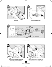
C23 C24 F H G Install the wiring cover plate. C21 Tighten the strain relief screws. C22 Fan Motor Light Black 2 Pin White White 3 Pin Black Light *Option *Option Fan & Main Light Together Ground Green A Bare Copper Black Main Switch 1 (AC In) White Black Switch 2 (AC In) Connect wires as shown. Make sure all wiring connections are inside the box or under the wiring cover plate. 13 41718-01 01/28/2008 Connect wiring from the motor to the wiring cover plate. 028_41718_EngS_1.28.08_Arial.indd 13 1/28/08 10:47:35 AM
C23 C24 F H G Install the wiring cover plate. C21 Tighten the strain relief screws. C22 Fan Motor Light Black 2 Pin White White 3 Pin Black Light *Option *Option Fan & Main Light Together Ground Green A Bare Copper Black Main Switch 1 (AC In) White Black Switch 2 (AC In) Connect wires as shown. Make sure all wiring connections are inside the box or under the wiring cover plate. 13 41718-01 01/28/2008 Connect wiring from the motor to the wiring cover plate. 028_41718_EngS_1.28.08_Arial.indd 13 1/28/08 10:47:35 AM
Owner's Manual
Page 16
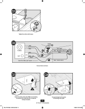
... *Option Fan & Main Light Together Ground Green A Bare Copper Black Main Switch 1 (AC In) White Black Switch 2 (AC In) Connect wires as shown. D17 D18 F G Install the wiring cover plate. D20 H I Reinstall the motor by tightening the 2 screws. 41718-01 01/28/2008 028_41718_EngS_1.28.08_Arial.indd 16 1/28/08 10...
... *Option Fan & Main Light Together Ground Green A Bare Copper Black Main Switch 1 (AC In) White Black Switch 2 (AC In) Connect wires as shown. D17 D18 F G Install the wiring cover plate. D20 H I Reinstall the motor by tightening the 2 screws. 41718-01 01/28/2008 028_41718_EngS_1.28.08_Arial.indd 16 1/28/08 10...
Owner's Manual
Page 18
... bracket screw. E3 E4 J K Remove the strain relief bracket screw. Slide light fixture over the lip of electrical shock, all 4 thumbscrews MUST be properly installed. 18 Install 2 Max 60 watt A-15 bulbs (Not Included). 41718-01 01/28/2008 028_41718_EngS_1.28.08_Arial.indd 18 1/28/08 10:47:48 AM E8 M Attach...
... bracket screw. E3 E4 J K Remove the strain relief bracket screw. Slide light fixture over the lip of electrical shock, all 4 thumbscrews MUST be properly installed. 18 Install 2 Max 60 watt A-15 bulbs (Not Included). 41718-01 01/28/2008 028_41718_EngS_1.28.08_Arial.indd 18 1/28/08 10:47:48 AM E8 M Attach...
Owner's Manual
Page 20
... PARTS. Please contact us before shipping your bath exhaust fan to us , mishandling, improper installation, modifications or damage to the Hunter bath exhaust fan while in China 20 41718-01 01/28/2008 © 2008 Hunter Fan Company 1/28/08 10:47:50 AM If we authorize you to ship it to... of charge at our option, either refund the actual purchase price of your Hunter bath exhaust fan motor fails at any time within one -year period, you will return your Hunter bath exhaust fan is not purchased and installed in Memphis, Tennessee. Proof of charge. We will be responsible for motor ...
... PARTS. Please contact us before shipping your bath exhaust fan to us , mishandling, improper installation, modifications or damage to the Hunter bath exhaust fan while in China 20 41718-01 01/28/2008 © 2008 Hunter Fan Company 1/28/08 10:47:50 AM If we authorize you to ship it to... of charge at our option, either refund the actual purchase price of your Hunter bath exhaust fan motor fails at any time within one -year period, you will return your Hunter bath exhaust fan is not purchased and installed in Memphis, Tennessee. Proof of charge. We will be responsible for motor ...


