Owner's Manual
Page 2
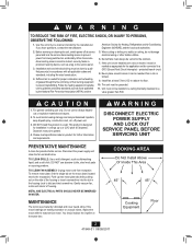
...motor bearings are making excessive or unusual noises, replace the motor with all applicable codes and standards, including fire-rated construction. 4. Installation work and electrical wiring must be marked as appropriate for the application and be reached from a tub or shower. 9. When cutting... LOCK OUT SERVICE PANEL BEFORE SERVICING UNIT PREVENTATIVE MAINTENANCE A clean fan provides better service. When the service disconnecting means cannot be installed in accordance with the exact service motor. If you have questions, contact the manufacturer. If this unit only in a wall....
...motor bearings are making excessive or unusual noises, replace the motor with all applicable codes and standards, including fire-rated construction. 4. Installation work and electrical wiring must be marked as appropriate for the application and be reached from a tub or shower. 9. When cutting... LOCK OUT SERVICE PANEL BEFORE SERVICING UNIT PREVENTATIVE MAINTENANCE A clean fan provides better service. When the service disconnecting means cannot be installed in accordance with the exact service motor. If you have questions, contact the manufacturer. If this unit only in a wall....
Owner's Manual
Page 3
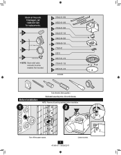
... M 96373-01-214 N 75184-01-133 O 96374-01-214 Included. Check all packing materials before installation. 2 J F Turn off the power source. 3 41949-01 09/09/2011 Loosen screws. Before Installation 1 Tools Needed. (Not supplied.) Estimated assembly time: 30 to 60 minutes NOTE: Remove all the ...parts. x5 A *B *C 3/8" Cable Connector x2 D Extra Screws * NOTE: Strain relief cable connector must be installed. Not Included. If damaged, call...
... M 96373-01-214 N 75184-01-133 O 96374-01-214 Included. Check all packing materials before installation. 2 J F Turn off the power source. 3 41949-01 09/09/2011 Loosen screws. Before Installation 1 Tools Needed. (Not supplied.) Estimated assembly time: 30 to 60 minutes NOTE: Remove all the ...parts. x5 A *B *C 3/8" Cable Connector x2 D Extra Screws * NOTE: Strain relief cable connector must be installed. Not Included. If damaged, call...
Owner's Manual
Page 5
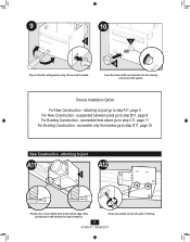
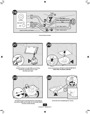
... 11 For Existing Construction - attaching to step D11, page 15 New Construction - accessible only from above go to step A11, page 5 For New Construction - Choose Installation Option For New Construction - attaching to joist go to step B11, page 8 For Existing Construction - Use second if needed. Screw pre-loaded screws into the...
... 11 For Existing Construction - attaching to step D11, page 15 New Construction - accessible only from above go to step A11, page 5 For New Construction - Choose Installation Option For New Construction - attaching to joist go to step B11, page 8 For Existing Construction - Use second if needed. Screw pre-loaded screws into the...
Owner's Manual
Page 6
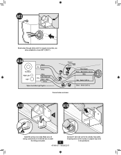
... Together Ground Green A Bare Copper Black Main Switch 1 (AC In) White Red Switch 1 (AC In) Black Switch 2 (AC In) Connect wires as shown. A15 A016 F H Install the wiring cover plate. Tape joints. Connect 4" duct and vent to be purchased. 6 41949-01 09/09/2011 For supply connection, use wires suitable for...
... Together Ground Green A Bare Copper Black Main Switch 1 (AC In) White Red Switch 1 (AC In) Black Switch 2 (AC In) Connect wires as shown. A15 A016 F H Install the wiring cover plate. Tape joints. Connect 4" duct and vent to be purchased. 6 41949-01 09/09/2011 For supply connection, use wires suitable for...
Owner's Manual
Page 9
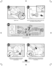
B17 B18 Tighten screws. B20 B21 G H Install the wiring cover plate. If ducting does not fit securely, an adapter may need to the outside. Tape joints. For supply connection, use wires suitable ...
B17 B18 Tighten screws. B20 B21 G H Install the wiring cover plate. If ducting does not fit securely, an adapter may need to the outside. Tape joints. For supply connection, use wires suitable ...
Owner's Manual
Page 13
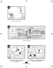
C23 C24 G I H Install the wiring cover plate. C21 Tighten the strain relief screws. DO NOT ALLOW THE MOTOR TO HANG FROM THE WIRING HARNESS. 13 41949-01 09/09/2011 Connect wiring harness. C22 Fan Motor Night Light Light Black 2 Pin White 3 Pin White Red Night Light Black Light *Option *Option Fan & Main Light Together Ground Green A Bare Copper Black Main Switch 1 (AC In) White Red Switch 1 (AC In) Black Switch 2 (AC In) Connect wires as shown. Make sure all wiring connections are inside the box or under the wiring cover plate.
C23 C24 G I H Install the wiring cover plate. C21 Tighten the strain relief screws. DO NOT ALLOW THE MOTOR TO HANG FROM THE WIRING HARNESS. 13 41949-01 09/09/2011 Connect wiring harness. C22 Fan Motor Night Light Light Black 2 Pin White 3 Pin White Red Night Light Black Light *Option *Option Fan & Main Light Together Ground Green A Bare Copper Black Main Switch 1 (AC In) White Red Switch 1 (AC In) Black Switch 2 (AC In) Connect wires as shown. Make sure all wiring connections are inside the box or under the wiring cover plate.
Owner's Manual
Page 15
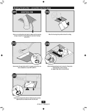
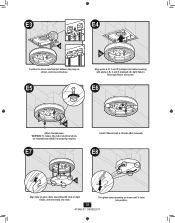
... from below D11 EXISTING FAN D12 F Remove an existing fan and check to make sure the opening is large enough to duct connector. Tape joints. F Install the housing flush with the sheetrock and secure by tightening the pre-loaded screws into position above the ceiling D13 D14 2 1 Route wires through strain...
... from below D11 EXISTING FAN D12 F Remove an existing fan and check to make sure the opening is large enough to duct connector. Tape joints. F Install the housing flush with the sheetrock and secure by tightening the pre-loaded screws into position above the ceiling D13 D14 2 1 Route wires through strain...
Owner's Manual
Page 16
... the wires are inside the box or under the wiring cover plate. DO NOT ALLOW THE MOTOR TO HANG FROM THE WIRING HARNESS. D17 D18 G H Install the wiring cover plate. Make sure all wiring connections are not pinched between the motor and the housing. 16 Secure the motor by inserting the...
... the wires are inside the box or under the wiring cover plate. DO NOT ALLOW THE MOTOR TO HANG FROM THE WIRING HARNESS. D17 D18 G H Install the wiring cover plate. Make sure all wiring connections are not pinched between the motor and the housing. 16 Secure the motor by inserting the...
Owner's Manual
Page 18
...) with slots on glass dome assembly with posts A, B, C and D (stamped into slots. WARNING: To reduce the risk of electrical shock, all 4 thumbscrews MUST be properly installed. E6 N Attach thumbscrews. E8 O Align tabs on light fixture, and insert tabs into light fixture). Slide light fixture over posts. Turn glass dome assembly as...
...) with slots on glass dome assembly with posts A, B, C and D (stamped into slots. WARNING: To reduce the risk of electrical shock, all 4 thumbscrews MUST be properly installed. E6 N Attach thumbscrews. E8 O Align tabs on light fixture, and insert tabs into light fixture). Slide light fixture over posts. Turn glass dome assembly as...
Owner's Manual
Page 20
...you will be responsible for any such damage. To obtain servicing, contact the nearest Hunter authorized service center of purchase is not purchased and installed in the U.S.A. We will return your Hunter bath exhaust fan is required when requesting warranty service. THE WARRANTY GIVES YOU SPECIFIC...not authorized by us, use , including failure to us , mishandling, improper installation, modifications or damage to the Hunter bath exhaust fan while in China 20 41949-01 09/09/2011 © 2011 Hunter Fan Company NO WARRANTY, EXPRESS OR IMPLIED, INCLUDING ANY WARRANTY OF MERCHANTABILITY OR...
...you will be responsible for any such damage. To obtain servicing, contact the nearest Hunter authorized service center of purchase is not purchased and installed in the U.S.A. We will return your Hunter bath exhaust fan is required when requesting warranty service. THE WARRANTY GIVES YOU SPECIFIC...not authorized by us, use , including failure to us , mishandling, improper installation, modifications or damage to the Hunter bath exhaust fan while in China 20 41949-01 09/09/2011 © 2011 Hunter Fan Company NO WARRANTY, EXPRESS OR IMPLIED, INCLUDING ANY WARRANTY OF MERCHANTABILITY OR...


