
Installation Guide
Page 1
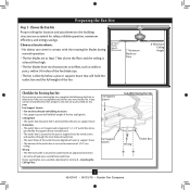
...box is directly below the joist or support brace. o e outer holes of the fan and light kit. o Six inches of the ceiling. Locate the site for your new Hunter fan. If NOT, install a support brace as described on this page. Attach the outlet box ... light kit. Step 4 Step 4 Install the Outlet Box 4-1. CAUTION: All wiring must be in the off . Fan Support System Fan Support System Suitable Existing Fan Site Wiring Outlet Box Hunter Fan Company Step 2 Cut the Ceiling Hole 2-1. Obtain a UL-approved octagonal 4" x 1-1/2" outlet box, plus two #8 x 1-1/2" ...
...box is directly below the joist or support brace. o e outer holes of the fan and light kit. o Six inches of the ceiling. Locate the site for your new Hunter fan. If NOT, install a support brace as described on this page. Attach the outlet box ... light kit. Step 4 Step 4 Install the Outlet Box 4-1. CAUTION: All wiring must be in the off . Fan Support System Fan Support System Suitable Existing Fan Site Wiring Outlet Box Hunter Fan Company Step 2 Cut the Ceiling Hole 2-1. Obtain a UL-approved octagonal 4" x 1-1/2" outlet box, plus two #8 x 1-1/2" ...
Owner's Manual
Page 1
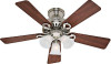
Date Purchased Where Purchased Type 2 Models Owner's Guide and Installation Manual English Español Form# 42439-01 20100615 ©2010 Hunter Fan Co. For Your Records and Warranty Assistance For reference, also attach your receipt or a copy of your receipt to the manual. Model Name Model No.
Date Purchased Where Purchased Type 2 Models Owner's Guide and Installation Manual English Español Form# 42439-01 20100615 ©2010 Hunter Fan Co. For Your Records and Warranty Assistance For reference, also attach your receipt or a copy of your receipt to the manual. Model Name Model No.
Owner's Manual
Page 2
...the risk of fire, electrical shock, or motor damage, do not bend the blade attachment system when installing, balancing, or cleaning the fan. Use only Hunter speed controls. • This product conforms to UL STD 507 and is certified to STD C22.2 No.113 • Wash your...and associated wall switch location. If you complete instructions for many years. Welcome Your new Hunter® ceiling fan is complete. © 2010 Hunter Fan Company 2 42439-01 • 06/15/10 • Hunter Fan Company This installation and operation manual gives you cannot lock the circuit breakers in the ...
...the risk of fire, electrical shock, or motor damage, do not bend the blade attachment system when installing, balancing, or cleaning the fan. Use only Hunter speed controls. • This product conforms to UL STD 507 and is certified to STD C22.2 No.113 • Wash your...and associated wall switch location. If you complete instructions for many years. Welcome Your new Hunter® ceiling fan is complete. © 2010 Hunter Fan Company 2 42439-01 • 06/15/10 • Hunter Fan Company This installation and operation manual gives you cannot lock the circuit breakers in the ...
Owner's Manual
Page 3
...an approved connector. • Six inches of the fan and light kit. Fan Support System • Fan attaches directly to Section 2 • Installing the Ceiling Plate. If your new Hunter fan. Choose the Fan Site Proper ceiling fan location and attachment to the building structure are at... • e electrical cable is directly below the joist or support brace. Fan Support System Fan Support System Suitable Existing Fan Site Wiring Outlet Box 3 42439-01 • 06/15/10 • Hunter Fan Company Outlet Box • e outlet box is an UL-approved octagonal 4"...
...an approved connector. • Six inches of the fan and light kit. Fan Support System • Fan attaches directly to Section 2 • Installing the Ceiling Plate. If your new Hunter fan. Choose the Fan Site Proper ceiling fan location and attachment to the building structure are at... • e electrical cable is directly below the joist or support brace. Fan Support System Fan Support System Suitable Existing Fan Site Wiring Outlet Box 3 42439-01 • 06/15/10 • Hunter Fan Company Outlet Box • e outlet box is an UL-approved octagonal 4"...
Owner's Manual
Page 4
...or support brace. 4-3. Install the Outlet Box 4-1. You will use a qualified electrician. 4 42439-01 • 06/15/10 • Hunter Fan Company If the joist is there, determine if it to allow you cannot lock the circuit breakers in the off . Position it is a ... switch location are unfamiliar with an approved connector, available at least 6" beyond the box. 5-3. Steps 2 - 3 3-2. For instructions to install your ceiling fan site. Cut a 4" diameter hole through the inner holes of 1/16" into the ceiling. If NOT, install a support brace as a tag, to...
...or support brace. 4-3. Install the Outlet Box 4-1. You will use a qualified electrician. 4 42439-01 • 06/15/10 • Hunter Fan Company If the joist is there, determine if it to allow you cannot lock the circuit breakers in the off . Position it is a ... switch location are unfamiliar with an approved connector, available at least 6" beyond the box. 5-3. Steps 2 - 3 3-2. For instructions to install your ceiling fan site. Cut a 4" diameter hole through the inner holes of 1/16" into the ceiling. If NOT, install a support brace as a tag, to...
Owner's Manual
Page 5
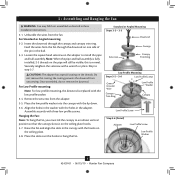
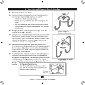
...ceilings higher than 8 feet high CAUTION: To reduce the risk of personal injury, attach the fan directly to the support structure of your Hunter fan in this manual include instructions for ceilings less than 8 feet, you maximum installation flexibility and ease.... Understanding Mounting and Installer's Choice® Hunter's patented 3-position mounting system provides you can install your Hunter fan, use the accessories, follow the instructions included with each product. All Hunter fans use sturdy 3/4" diameter pipe to these instructions, and use ...
...ceilings higher than 8 feet high CAUTION: To reduce the risk of personal injury, attach the fan directly to the support structure of your Hunter fan in this manual include instructions for ceilings less than 8 feet, you maximum installation flexibility and ease.... Understanding Mounting and Installer's Choice® Hunter's patented 3-position mounting system provides you can install your Hunter fan, use the accessories, follow the instructions included with each product. All Hunter fans use sturdy 3/4" diameter pipe to these instructions, and use ...
Owner's Manual
Page 6
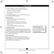
...pliers • Ladder (height dependent upon installation site) Checking Your Fan Parts Carefully unpack your Hunter dealer or call Hunter Technical Support Department at 888-830-1326 (In Canada, call 1-866-268-1936). Proper ceiling fan location and attachment to the included Parts Guide. If you can...if applicable) in sets, as they were shipped. 6 42439-01 • 06/15/10 • Hunter Fan Company Gathering the Tools You will need help installing the fan, your Hunter fan dealer can do the following tools for and install wood screws. • Identify and connect electrical wires. ...
...pliers • Ladder (height dependent upon installation site) Checking Your Fan Parts Carefully unpack your Hunter dealer or call Hunter Technical Support Department at 888-830-1326 (In Canada, call 1-866-268-1936). Proper ceiling fan location and attachment to the included Parts Guide. If you can...if applicable) in sets, as they were shipped. 6 42439-01 • 06/15/10 • Hunter Fan Company Gathering the Tools You will need help installing the fan, your Hunter fan dealer can do the following tools for and install wood screws. • Identify and connect electrical wires. ...
Owner's Manual
Page 7
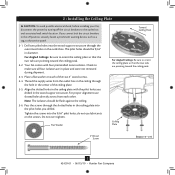
...the hole in the center of the two 3" wood screws. 2-4. Ceiling Plate 3" Wood Screw Steps 2-3 - 2-6 7 42439-01 • 06/15/10 • Hunter Fan Company Pass the screws through the outermost holes in the ceiling plate with four preinstalled noise isolators. Do not over tighten. Place a flat washer on... the slotted holes in the ceiling plate into the pilot holes you cannot lock the circuit breakers in the wood support structure. Your fan comes with the pilot holes you drilled in the off the circuit breakers to the outlet box and associated wall switch location. Thread ...
...the hole in the center of the two 3" wood screws. 2-4. Ceiling Plate 3" Wood Screw Steps 2-3 - 2-6 7 42439-01 • 06/15/10 • Hunter Fan Company Pass the screws through the outermost holes in the ceiling plate with four preinstalled noise isolators. Do not over tighten. Place a flat washer on... the slotted holes in the ceiling plate into the pilot holes you cannot lock the circuit breakers in the wood support structure. Your fan comes with the pilot holes you drilled in the off the circuit breakers to the outlet box and associated wall switch location. Thread ...
Owner's Manual
Page 8
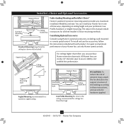
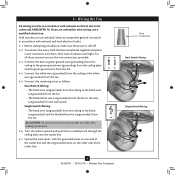
...Washer Canopy Low Profile Screw Step 3-6 (Detail) Adapter Low Profile Screw Low Profile Washer 8 42439-01 • 06/15/10 • Hunter Fan Company Loosen the square head setscrew on the ceiling plate hooks. 3-7. Securely retighten the setscrew with the hooks on the pipe will still be ...visible; Remove the setscrew from the fan. Raise the fan and align the slots in the canopy with a wrench or pliers. Unbundle the wires from the adapter. 3-5. Align the holes in ...
...Washer Canopy Low Profile Screw Step 3-6 (Detail) Adapter Low Profile Screw Low Profile Washer 8 42439-01 • 06/15/10 • Hunter Fan Company Loosen the square head setscrew on the ceiling plate hooks. 3-7. Securely retighten the setscrew with the hooks on the pipe will still be ...visible; Remove the setscrew from the fan. Raise the fan and align the slots in the canopy with a wrench or pliers. Unbundle the wires from the adapter. 3-5. Align the holes in ...
Owner's Manual
Page 9
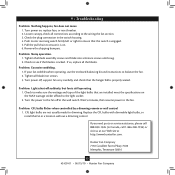
... outlet box and the ungrounded wires on the other side of the outlet box. 9 42439-01 • 06/15/10 • Hunter Fan Company Wire Connector Dual Switch Wiring Single Switch Wiring Connect the remaining wires as follows: Dual Switch Wiring: • The black wire (...Switch Wiring: • The black wire (ungrounded) from the ceiling to the black (ungrounded) and the black/white wire (ungrounded) from the fan. 4-5. Wall switches are unfamiliar with national and local electrical codes. 4-1. For all these connections use a qualified electrician. Connect the white wire (grounded...
... outlet box and the ungrounded wires on the other side of the outlet box. 9 42439-01 • 06/15/10 • Hunter Fan Company Wire Connector Dual Switch Wiring Single Switch Wiring Connect the remaining wires as follows: Dual Switch Wiring: • The black wire (...Switch Wiring: • The black wire (ungrounded) from the ceiling to the black (ungrounded) and the black/white wire (ungrounded) from the fan. 4-5. Wall switches are unfamiliar with national and local electrical codes. 4-1. For all these connections use a qualified electrician. Connect the white wire (grounded...
Owner's Manual
Page 10
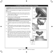
...trim ring. Step 5-1 Tab Groove Step 5-2 Step 5-3 Canopy Canopy Trim Ring Canopy Screw 10 42439-01 • 06/15/10 • Hunter Fan Company When all three canopy screws. 5-5. Align the tabs on opposite sides of the canopy. 5 • Installing the Canopy and Canopy Trim Ring... WARNING: Failure to complete the following steps. 5-1. WARNING: The slots in the hanger ball. Swing the fan up to fall. Note: Should you use a magnetic tip screwdriver for alignment. 5-3. Note: It is secure in the canopy. Partially install a ...
...trim ring. Step 5-1 Tab Groove Step 5-2 Step 5-3 Canopy Canopy Trim Ring Canopy Screw 10 42439-01 • 06/15/10 • Hunter Fan Company When all three canopy screws. 5-5. Align the tabs on opposite sides of the canopy. 5 • Installing the Canopy and Canopy Trim Ring... WARNING: Failure to complete the following steps. 5-1. WARNING: The slots in the hanger ball. Swing the fan up to fall. Note: Should you use a magnetic tip screwdriver for alignment. 5-3. Note: It is secure in the canopy. Partially install a ...
Owner's Manual
Page 11
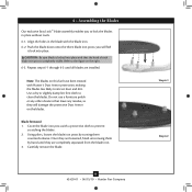
...as they are loosened, finish unscrewing them by turning them counterclockwise. you to prevent scratching the blades. 2. Cover the blade iron posts with Hunter's Dust Armor protection, making the blades less likely to attract dust and dirt. CAUTION: Be sure blade is locked into place. Note: The...blades. Carefully remove the blade. 11 42439-01 • 06/15/10 • Hunter Fan Company Step 6-1 Step 6-2 Blade Removal: 1. Use a dry or slightly damp lint free cloth to the figure on this fan have been treated with a protective cloth to lock the blades in the blade with ...
...as they are loosened, finish unscrewing them by turning them counterclockwise. you to prevent scratching the blades. 2. Cover the blade iron posts with Hunter's Dust Armor protection, making the blades less likely to attract dust and dirt. CAUTION: Be sure blade is locked into place. Note: The...blades. Carefully remove the blade. 11 42439-01 • 06/15/10 • Hunter Fan Company Step 6-1 Step 6-2 Blade Removal: 1. Use a dry or slightly damp lint free cloth to the figure on this fan have been treated with a protective cloth to lock the blades in the blade with ...
Owner's Manual
Page 12
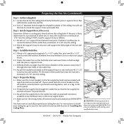
...Tighten all three screws securely. Notch Note: In compliance with US federal energy regulations, this fan model. 7-1. Install the third housing assembly screw. 7-5. Exceeding the wattage limit marked on ...Plug Connector Housing Assembly Screw WARNING: Use only the light fixture supplied with this ceiling fan contains a device that restricts its light output. Make sure the connectors are polarized ... lower switch housing with the screws on the MAX wattage sticker affixed to the fan, partially install two housing assembly screws into the upper switch housing. 7-2. Steps 7-3 - ...
...Tighten all three screws securely. Notch Note: In compliance with US federal energy regulations, this fan model. 7-1. Install the third housing assembly screw. 7-5. Exceeding the wattage limit marked on ...Plug Connector Housing Assembly Screw WARNING: Use only the light fixture supplied with this ceiling fan contains a device that restricts its light output. Make sure the connectors are polarized ... lower switch housing with the screws on the MAX wattage sticker affixed to the fan, partially install two housing assembly screws into the upper switch housing. 7-2. Steps 7-3 - ...
Owner's Manual
Page 13
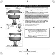
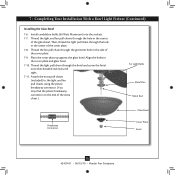
... the cover plate. 7-8. 7 • Completing Your Installation With a Bowl Light Fixture (Continued) Installing the Glass Bowl 7-6. Thread the light and fan pull chains through the hole in the center of the extra chain.) For Light Bulbs Metal Disc Metal Rod Glass Bowl Breakaway Connector Cover Plate... Finial 13 42439-01 • 06/15/10 • Hunter Fan Company Attach the extra pull chains (included) to the light and fan pull chains using the plastic breakaway connector. (You may find the plastic breakaway connector on the end ...
... the cover plate. 7-8. 7 • Completing Your Installation With a Bowl Light Fixture (Continued) Installing the Glass Bowl 7-6. Thread the light and fan pull chains through the hole in the center of the extra chain.) For Light Bulbs Metal Disc Metal Rod Glass Bowl Breakaway Connector Cover Plate... Finial 13 42439-01 • 06/15/10 • Hunter Fan Company Attach the extra pull chains (included) to the light and fan pull chains using the plastic breakaway connector. (You may find the plastic breakaway connector on the end ...
Owner's Manual
Page 14
...the room without causing a draft. 8-5. Slide the reversing switch on electrical power to prevent the chain from recoiling into the connector. 8-3. The fan pull chain controls power to clean the blades. The chain has two settings: ON and OFF. 8-4. For cleaning finishes, use upward air flow...-01 • 06/15/10 • Hunter Fan Company To Change Airflow Direction Turn the fan off and let it come to the light fixture. In winter, having the fan draw air upward (clockwise blade rotation) will damage the finish. Restart fan. The blades on this happens, simply reinsert ...
...the room without causing a draft. 8-5. Slide the reversing switch on electrical power to prevent the chain from recoiling into the connector. 8-3. The fan pull chain controls power to clean the blades. The chain has two settings: ON and OFF. 8-4. For cleaning finishes, use upward air flow...-01 • 06/15/10 • Hunter Fan Company To Change Airflow Direction Turn the fan off and let it come to the light fixture. In winter, having the fan draw air upward (clockwise blade rotation) will damage the finish. Restart fan. The blades on this happens, simply reinsert ...
Owner's Manual
Page 15
... the power to make sure the wattage and type of the light bulbs that are not usually made for dimming. Check to the fan off , support fan very carefully, and check that the switch is cracked. CFL light bulbs are installed meet the specifications on , replace fuse, or ...1. Push motor reversing switch firmly left or right to the light socket. 2. Turn power off at http://www.hunterfan.com. Hunter Fan Company 7130 Goodlett Farms Pkwy. #400 Memphis, Tennessee 38016 15 42439-01 • 06/15/10 • Hunter Fan Company fan does not move. 1. Tighten all blade iron screws. 3.
... the power to make sure the wattage and type of the light bulbs that are not usually made for dimming. Check to the fan off , support fan very carefully, and check that the switch is cracked. CFL light bulbs are installed meet the specifications on , replace fuse, or ...1. Push motor reversing switch firmly left or right to the light socket. 2. Turn power off at http://www.hunterfan.com. Hunter Fan Company 7130 Goodlett Farms Pkwy. #400 Memphis, Tennessee 38016 15 42439-01 • 06/15/10 • Hunter Fan Company fan does not move. 1. Tighten all blade iron screws. 3.
Parts Guide
Page 1
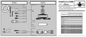
Dwg. # G0858-01 28683 G0858-02 28684 G0858-03 28736 G0858-04 Finish Qnty 1 White Brushed Nickel New... 03077-07 03077-07 3 77646-04 77646-04 77646-04 77646-04 1 65666-01 65666-01 65666-01 65666-01 Hunter Fan Company • 7130 Goodlett Farms Pkwy. #400 • Memphis, TN 38016 • www.hunterfan.com • 98000...Wire x 4 Connector x 10 x 3 Thumb Screw Screw, Switch Housing Assembly Hanger Bracket Assembly Blade Assembly Switch Housing Assembly Fan Parts (Not Drawn to Scale) PARTS GUIDE Using this Parts Guide, make sure all parts are missing, DO NOT RETURN THIS...
Dwg. # G0858-01 28683 G0858-02 28684 G0858-03 28736 G0858-04 Finish Qnty 1 White Brushed Nickel New... 03077-07 03077-07 3 77646-04 77646-04 77646-04 77646-04 1 65666-01 65666-01 65666-01 65666-01 Hunter Fan Company • 7130 Goodlett Farms Pkwy. #400 • Memphis, TN 38016 • www.hunterfan.com • 98000...Wire x 4 Connector x 10 x 3 Thumb Screw Screw, Switch Housing Assembly Hanger Bracket Assembly Blade Assembly Switch Housing Assembly Fan Parts (Not Drawn to Scale) PARTS GUIDE Using this Parts Guide, make sure all parts are missing, DO NOT RETURN THIS...


