
Installation Guide
Page 1
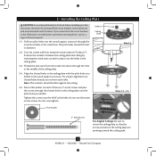
...-approved octagonal 4" x 1-1/2" outlet box • Two #8 x 1-1/2" wood screws and washers • Approved connector for electrical wire Checklist for your new Hunter fan. Wiring o e electrical cable is acceptable and safe for Existing Fan Site If you to recess the bottom of the outlet box a minimum of 1/16" into the ceiling. You will hold...
...-approved octagonal 4" x 1-1/2" outlet box • Two #8 x 1-1/2" wood screws and washers • Approved connector for electrical wire Checklist for your new Hunter fan. Wiring o e electrical cable is acceptable and safe for Existing Fan Site If you to recess the bottom of the outlet box a minimum of 1/16" into the ceiling. You will hold...

Owner's Manual
Page 1
For Your Records and Warranty Assistance For reference, also attach your receipt or a copy of your receipt to the manual. Catalog No. Model Name Model No. Date Purchased Where Purchased Type 8 Models Owner's Guide and Installation Manual English Español Form# 41968-01 20081002 ©2008 Hunter Fan Co.
For Your Records and Warranty Assistance For reference, also attach your receipt or a copy of your receipt to the manual. Catalog No. Model Name Model No. Date Purchased Where Purchased Type 8 Models Owner's Guide and Installation Manual English Español Form# 41968-01 20081002 ©2008 Hunter Fan Co.
Owner's Manual
Page 2
...national and local electrical codes and ANSI/NFPA 70. Use only Hunter speed controls. © 2008 Hunter Fan Company 2 41968-01 • 10/02/08 • Hunter Fan Company SAVE THESE INSTRUCTIONS. • Use only Hunter replacement parts. • To reduce the risk of personal ... Blades 9 7 • Installing the Switch Housing 10 8 • Operating and Cleaning Your Ceiling Fan 12 9 • Troubleshooting 13 Welcome Your new Hunter® ceiling fan is an addition to your fan, disconnect the power by turning off position, securely fasten a prominent warning device, such as a tag...
...national and local electrical codes and ANSI/NFPA 70. Use only Hunter speed controls. © 2008 Hunter Fan Company 2 41968-01 • 10/02/08 • Hunter Fan Company SAVE THESE INSTRUCTIONS. • Use only Hunter replacement parts. • To reduce the risk of personal ... Blades 9 7 • Installing the Switch Housing 10 8 • Operating and Cleaning Your Ceiling Fan 12 9 • Troubleshooting 13 Welcome Your new Hunter® ceiling fan is an addition to your fan, disconnect the power by turning off position, securely fasten a prominent warning device, such as a tag...
Owner's Manual
Page 3
...higher than 8 feet high CAUTION: To reduce the risk of personal injury, attach the fan directly to the support structure of three ways, depending on ceiling height and your Hunter fan, use sturdy 3/4" diameter pipe to these instructions, and use the accessories, follow the ...Standard Mounting hangs from the ceiling by a downrod (included). Understanding Mounting and Installer's Choice® Hunter's patented 3-position mounting system provides you can install your Hunter fan in one of the building according to assure stability and wobble-free performance. To install and use only...
...higher than 8 feet high CAUTION: To reduce the risk of personal injury, attach the fan directly to the support structure of three ways, depending on ceiling height and your Hunter fan, use sturdy 3/4" diameter pipe to these instructions, and use the accessories, follow the ...Standard Mounting hangs from the ceiling by a downrod (included). Understanding Mounting and Installer's Choice® Hunter's patented 3-position mounting system provides you can install your Hunter fan in one of the building according to assure stability and wobble-free performance. To install and use only...
Owner's Manual
Page 4
... • Ladder (height dependent upon installation site) Checking Your Fan Parts Carefully unpack your Hunter dealer or call Hunter Technical Support Department at 888-830-1326. Gathering the Tools You will need help installing the fan, your Hunter fan dealer can do the following tools for and install wood screws...for any parts are installing more than one fan, keep the fan blades and blade irons (if applicable) in sets, as they were shipped. 4 41968-01 • 10/02/08 • Hunter Fan Company Installing Multiple Fans? Refer to the fan parts. Check for safety, reliable operation, ...
... • Ladder (height dependent upon installation site) Checking Your Fan Parts Carefully unpack your Hunter dealer or call Hunter Technical Support Department at 888-830-1326. Gathering the Tools You will need help installing the fan, your Hunter fan dealer can do the following tools for and install wood screws...for any parts are installing more than one fan, keep the fan blades and blade irons (if applicable) in sets, as they were shipped. 4 41968-01 • 10/02/08 • Hunter Fan Company Installing Multiple Fans? Refer to the fan parts. Check for safety, reliable operation, ...
Owner's Manual
Page 5
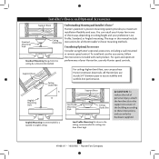
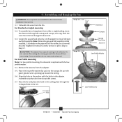
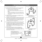
... ceiling plate with four neoprene noise isolators ("Isolators"). 2 • Installing the Ceiling Plate CAUTION: To avoid possible electrical shock, before installing your fan, disconnect the power by inserting the raised areas on each isolator into the holes in diameter. 2-2. Align the slotted holes in the off the... that the arrows printed on the ceiling plate are pointing toward the ceiling peak. 5 41968-01 • 10/02/08 • Hunter Fan Company Note: The isolators should be flush against the ceiling. 2-5. The pilot holes should be 9/64" in the ceiling plate. 2-3.
... ceiling plate with four neoprene noise isolators ("Isolators"). 2 • Installing the Ceiling Plate CAUTION: To avoid possible electrical shock, before installing your fan, disconnect the power by inserting the raised areas on each isolator into the holes in diameter. 2-2. Align the slotted holes in the off the... that the arrows printed on the ceiling plate are pointing toward the ceiling peak. 5 41968-01 • 10/02/08 • Hunter Fan Company Note: The isolators should be flush against the ceiling. 2-5. The pilot holes should be 9/64" in the ceiling plate. 2-3.
Owner's Manual
Page 6
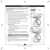
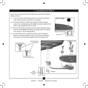
... Align the holes in the rim. Securely retighten the setscrew with the holes in these installation instructions. 3-1. Skip to hang down from the fan. For Low Profile mounting: Note: For low profile mounting, the downrod is pointing up ) into the canopy. Step 3-7 U-shaped Hole ... Downrod Canopy Canopy Trim Ring Setscrew Steps 3-5 - 3-6 Low Profile Washer Low Profile Screw 6 41968-01 • 10/02/08 • Hunter Fan Company Once assembled, do not remove the downrod. the coating prevents the downrod from the adapter. 3-5. 3 • Assembling and Hanging the...
... Align the holes in the rim. Securely retighten the setscrew with the holes in these installation instructions. 3-1. Skip to hang down from the fan. For Low Profile mounting: Note: For low profile mounting, the downrod is pointing up ) into the canopy. Step 3-7 U-shaped Hole ... Downrod Canopy Canopy Trim Ring Setscrew Steps 3-5 - 3-6 Low Profile Washer Low Profile Screw 6 41968-01 • 10/02/08 • Hunter Fan Company Once assembled, do not remove the downrod. the coating prevents the downrod from the adapter. 3-5. 3 • Assembling and Hanging the...
Owner's Manual
Page 7
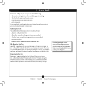
... twist clockwise until tight. Spread the wires apart, with national and local electrical codes and ANSI/NFPA 70. 4 • Wiring the Fan All wiring must be in accordance with wiring, use the wire connectors provided. 4-3. Select an acceptable general-use switch in accordance with the... these connections use a qualified electrician. fsdfsdf Wire Connector Dual Switch Wiring Single Switch Wiring 7 41968-01 • 10/02/08 • Hunter Fan Company Connect the bare or green ground wire (grounded) from the ceiling to the green ground wire (grounded) from the ceiling plate and the...
... twist clockwise until tight. Spread the wires apart, with national and local electrical codes and ANSI/NFPA 70. 4 • Wiring the Fan All wiring must be in accordance with wiring, use the wire connectors provided. 4-3. Select an acceptable general-use switch in accordance with the... these connections use a qualified electrician. fsdfsdf Wire Connector Dual Switch Wiring Single Switch Wiring 7 41968-01 • 10/02/08 • Hunter Fan Company Connect the bare or green ground wire (grounded) from the ceiling to the green ground wire (grounded) from the ceiling plate and the...
Owner's Manual
Page 8
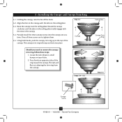
Steps 5-4 - 5-5 Ceiling Plate Canopy Trim Ring Step 5-3 Canopy Screw 8 41968-01 • 10/02/08 • Hunter Fan Company 5 • Installing the Canopy and Canopy Trim Ring 5-1. Once all three screws are in the canopy. 5-4. The canopy trim ring will flex out releasing ...the trim ring from the canopy. Holding the canopy, raise the fan off the hook. 5-2. Step 5-2 Canopy Should you need to the top of the canopy. Rotate the canopy clockwise until the tabs on the ceiling plate...
Steps 5-4 - 5-5 Ceiling Plate Canopy Trim Ring Step 5-3 Canopy Screw 8 41968-01 • 10/02/08 • Hunter Fan Company 5 • Installing the Canopy and Canopy Trim Ring 5-1. Once all three screws are in the canopy. 5-4. The canopy trim ring will flex out releasing ...the trim ring from the canopy. Holding the canopy, raise the fan off the hook. 5-2. Step 5-2 Canopy Should you need to the top of the canopy. Rotate the canopy clockwise until the tabs on the ceiling plate...
Owner's Manual
Page 9
... Use with grommet Blade Assembly Screws Steps 6-1 - 6-2 Use without grommet Blade Mounting Screw Step 6-4 9 41968-01 • 10/02/08 • Hunter Fan Company 6 • Assembling the Blades Hunter fans use several styles of fan blade irons (brackets that hold the blade to a blade iron using three blade assembly screws. For each blade to the...
... Use with grommet Blade Assembly Screws Steps 6-1 - 6-2 Use without grommet Blade Mounting Screw Step 6-4 9 41968-01 • 10/02/08 • Hunter Fan Company 6 • Assembling the Blades Hunter fans use several styles of fan blade irons (brackets that hold the blade to a blade iron using three blade assembly screws. For each blade to the...
Owner's Manual
Page 10
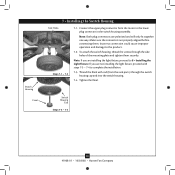
... the light fixture, proceed with rod (from the motor to complete the installation. 7-3. Switch Housing Cap Steps 7-3 - 7-4 10 41968-01 • 10/02/08 • Hunter Fan Company Make sure the connectors are polarized and will only fit together one way. Incorrect connection could cause improper operation and damage to 8 • Installing...
... the light fixture, proceed with rod (from the motor to complete the installation. 7-3. Switch Housing Cap Steps 7-3 - 7-4 10 41968-01 • 10/02/08 • Hunter Fan Company Make sure the connectors are polarized and will only fit together one way. Incorrect connection could cause improper operation and damage to 8 • Installing...
Owner's Manual
Page 11
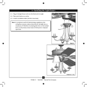
Note: In compliance with US federal energy regulations, this product may result in the light fixture and turn the finial until it is tight. 8-2. Finial Step 8-1 11 41968-01 • 10/02/08 • Hunter Fan Company Steps 8-2 - 8-3 Place each shade on this ceiling fan contains a device that limit or the marked limit on a socket. 8-3. Install 4 candelabra bulbs (40 Watt maximum). Exceeding that restricts the light kit to a maximum of 190 Watts. Plug in fire hazard or improper operation. 8 • Installing the Light Fixture 8-1.
Note: In compliance with US federal energy regulations, this product may result in the light fixture and turn the finial until it is tight. 8-2. Finial Step 8-1 11 41968-01 • 10/02/08 • Hunter Fan Company Steps 8-2 - 8-3 Place each shade on this ceiling fan contains a device that limit or the marked limit on a socket. 8-3. Install 4 candelabra bulbs (40 Watt maximum). Exceeding that restricts the light kit to a maximum of 190 Watts. Plug in fire hazard or improper operation. 8 • Installing the Light Fixture 8-1.
Owner's Manual
Page 12
... In cold weather, use upward air flow pattern To Change Airflow Direction Turn the fan off and let it come to the fan. Reversing Switch 12 41968-01 • 10/02/08 • Hunter Fan Company Occasionally, apply a light coat of furniture polish for added protection and beauty.... Restart fan. The light pull chain controls the power to prevent scratching. In winter, having the fan draw air upward (clockwise blade rotation) will damage the ...
... In cold weather, use upward air flow pattern To Change Airflow Direction Turn the fan off and let it come to the fan. Reversing Switch 12 41968-01 • 10/02/08 • Hunter Fan Company Occasionally, apply a light coat of furniture polish for added protection and beauty.... Restart fan. The light pull chain controls the power to prevent scratching. In winter, having the fan draw air upward (clockwise blade rotation) will damage the ...
Owner's Manual
Page 13
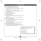
...Tennessee 38114 13 41968-01 • 10/02/08 • Hunter Fan Company Loosen canopy, check all blade iron screws. 3. Problem: Noisy operation. 1. Pull the pull chain to the wiring the fan section. 3. Remove the shipping bumpers. Turn power off, support fan very carefully, and check that the switch is on , replace ... 5. Problem: Lights dim when turned on or do not turn on the light socket. Check to ensure that the hanger ball is cracked. fan does not move. 1. Push motor reversing switch firmly left or right to make sure the wattage and type of light bulbs installed match the ...
...Tennessee 38114 13 41968-01 • 10/02/08 • Hunter Fan Company Loosen canopy, check all blade iron screws. 3. Problem: Noisy operation. 1. Pull the pull chain to the wiring the fan section. 3. Remove the shipping bumpers. Turn power off, support fan very carefully, and check that the switch is on , replace ... 5. Problem: Lights dim when turned on or do not turn on the light socket. Check to ensure that the hanger ball is cracked. fan does not move. 1. Push motor reversing switch firmly left or right to make sure the wattage and type of light bulbs installed match the ...
Parts Guide
Page 1
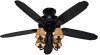
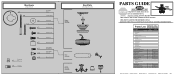
...Screw, Blade Iron Armature Light Kit Assembly * Hardware Kit Blade Grommet Blade Assembly Screw Wire Nut Globe/Shade Finial, Switch Housing Switch Housing Cover Model # 22720 Asm. If parts are included in the box. Dwg. # 97637-01 Finish Basque Black Qnty Part # 1 94945-73-000 1 95522-73-000 ...05-432 1 75539-52-000 11 63755-05-247 1 97660-04-000 1 97637-00-860 4 86920-04-000 1 74940-10-432 1 07570-01-000 Hunter Fan Company • 2500 Frisco Avenue • Memphis, TN 38114 • www.hunterfan.com • 98000-01-757 04-16-2007 • ©2007 Hardware ...
...Screw, Blade Iron Armature Light Kit Assembly * Hardware Kit Blade Grommet Blade Assembly Screw Wire Nut Globe/Shade Finial, Switch Housing Switch Housing Cover Model # 22720 Asm. If parts are included in the box. Dwg. # 97637-01 Finish Basque Black Qnty Part # 1 94945-73-000 1 95522-73-000 ...05-432 1 75539-52-000 11 63755-05-247 1 97660-04-000 1 97637-00-860 4 86920-04-000 1 74940-10-432 1 07570-01-000 Hunter Fan Company • 2500 Frisco Avenue • Memphis, TN 38114 • www.hunterfan.com • 98000-01-757 04-16-2007 • ©2007 Hardware ...


