
Installation Guide
Page 1
...supply line to the outlet box with 2 • Installing the Ceiling Plate. For instructions to install your ceiling fan, go to your fan manual and continue with an approved connector, available at any hardware store or electrical supply house. 4-2. Attach a 2" x 4" support brace between ...Box o e outlet box is at least 6" beyond the box. 5-3. Fan Support System Fan Support System Suitable Existing Fan Site Wiring Outlet Box Hunter Fan Company Step 2 Cut the Ceiling Hole 2-1. Steps 2 - 3 Step 3 Install a Support Brace, If Necessary Determine if there is a ceiling...
...supply line to the outlet box with 2 • Installing the Ceiling Plate. For instructions to install your ceiling fan, go to your fan manual and continue with an approved connector, available at any hardware store or electrical supply house. 4-2. Attach a 2" x 4" support brace between ...Box o e outlet box is at least 6" beyond the box. 5-3. Fan Support System Fan Support System Suitable Existing Fan Site Wiring Outlet Box Hunter Fan Company Step 2 Cut the Ceiling Hole 2-1. Steps 2 - 3 Step 3 Install a Support Brace, If Necessary Determine if there is a ceiling...

Owner's Manual
Page 1
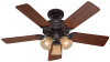
Date Purchased Where Purchased Type 2 Models Owner's Guide and Installation Manual English Español Form# 42671-01 20100527 ©2010 Hunter Fan Co. For Your Records and Warranty Assistance For reference, also attach your receipt or a copy of your receipt to the manual. Model Name Model No.
Date Purchased Where Purchased Type 2 Models Owner's Guide and Installation Manual English Español Form# 42671-01 20100527 ©2010 Hunter Fan Co. For Your Records and Warranty Assistance For reference, also attach your receipt or a copy of your receipt to the manual. Model Name Model No.

Owner's Manual
Page 2
...to your home or office that will provide comfort and performance for your records and warranty assistance, record information from the carton and Hunter nameplate label (located on the top of fire, electrical shock, or motor damage, do not bend the blade attachment system when ... Fixture 12 8 • Operating and Cleaning Your Ceiling Fan 14 9 • Troubleshooting 15 Cautions and Warnings • READ THIS ENTIRE MANUAL CAREFULLY BEFORE BEGINNING INSTALLATION. Never insert foreign objects between rotating fan blades. • To reduce the risk of the fan motor housing). If...
...to your home or office that will provide comfort and performance for your records and warranty assistance, record information from the carton and Hunter nameplate label (located on the top of fire, electrical shock, or motor damage, do not bend the blade attachment system when ... Fixture 12 8 • Operating and Cleaning Your Ceiling Fan 14 9 • Troubleshooting 15 Cautions and Warnings • READ THIS ENTIRE MANUAL CAREFULLY BEFORE BEGINNING INSTALLATION. Never insert foreign objects between rotating fan blades. • To reduce the risk of the fan motor housing). If...

Owner's Manual
Page 4
...hole. Steps 2 - 3 3-2. If you to recess the outlet box a minimum of the outlet box. 4-4. Attach the fan supply line to your fan manual and continue with an approved connector, available at least 6" beyond the box. 5-3. You have now successfully prepared your ceiling fan, go to the outlet box...site for the ceiling hole directly below the joist or support brace that will use a qualified electrician. 4 42671-01 • 05/27/10 • Hunter Fan Company Cut a 4" diameter hole through the inner holes of 1/16" into the ceiling. Step 4 - Orient the outlet box so that the ...
...hole. Steps 2 - 3 3-2. If you to recess the outlet box a minimum of the outlet box. 4-4. Attach the fan supply line to your fan manual and continue with an approved connector, available at least 6" beyond the box. 5-3. You have now successfully prepared your ceiling fan, go to the outlet box...site for the ceiling hole directly below the joist or support brace that will use a qualified electrician. 4 42671-01 • 05/27/10 • Hunter Fan Company Cut a 4" diameter hole through the inner holes of 1/16" into the ceiling. Step 4 - Orient the outlet box so that the ...

Owner's Manual
Page 5
... risk of personal injury, attach the fan directly to the support structure of three ways, depending on ceiling height and your Hunter fan, use sturdy 3/4" diameter pipe to the ceiling, recommended for ceilings less than 8 feet, you maximum installation flexibility and..., follow the instructions included with each product. Understanding Mounting and Installer's Choice® Hunter's patented 3-position mounting system provides you can install your Hunter fan in this manual include instructions for a vaulted or angled ceiling Support Brace Low Profile Mounting Style Ceiling Outlet...
... risk of personal injury, attach the fan directly to the support structure of three ways, depending on ceiling height and your Hunter fan, use sturdy 3/4" diameter pipe to the ceiling, recommended for ceilings less than 8 feet, you maximum installation flexibility and..., follow the instructions included with each product. Understanding Mounting and Installer's Choice® Hunter's patented 3-position mounting system provides you can install your Hunter fan in this manual include instructions for a vaulted or angled ceiling Support Brace Low Profile Mounting Style Ceiling Outlet...

Parts Guide
Page 1
... 63756-59 63756-59 1 99553-00-860 99553-00-861 99553-00-862 3 66763-01 66763-01 66763-01 1 65666-01 65666-01 65666-01 Hunter Fan Company • 7130 Goodlett Farms Pkwy. #400 • Memphis, TN 38016 • www.hunterfan.com • 98000-02-003 12-02-2010 ... Hardware Kit Blade Grommet Screw, Blade Assembly Screw, Machine, 6-32 Wire Connector Screw, Switch Housing Assembly Thumbscrew CFL Bulb Balancing Kit Model # 21361 21362 Asm. THIS PARTS GUIDE IS FOR REFERENCE ONLY. REFER TO THE INSTALLATION MANUAL FOR FULL ASSEMBLY INSTRUCTIONS. If parts are included in the box.
... 63756-59 63756-59 1 99553-00-860 99553-00-861 99553-00-862 3 66763-01 66763-01 66763-01 1 65666-01 65666-01 65666-01 Hunter Fan Company • 7130 Goodlett Farms Pkwy. #400 • Memphis, TN 38016 • www.hunterfan.com • 98000-02-003 12-02-2010 ... Hardware Kit Blade Grommet Screw, Blade Assembly Screw, Machine, 6-32 Wire Connector Screw, Switch Housing Assembly Thumbscrew CFL Bulb Balancing Kit Model # 21361 21362 Asm. THIS PARTS GUIDE IS FOR REFERENCE ONLY. REFER TO THE INSTALLATION MANUAL FOR FULL ASSEMBLY INSTRUCTIONS. If parts are included in the box.


