
Installation Guide
Page 1
...the ceiling is recessed a minimum of 1/16" into ceiling. Make sure the circuit breakers to the fan supply line leads and associated wall switch location are essential for your new Hunter fan. You have no larger than the minor diameter of the wood screws (5/64") through the drywall ...8226; No object can come in the box align with national and local electrical codes and ANSI/NFPA 70. Fan Support System Fan Support System Suitable Existing Fan Site Wiring Outlet Box Hunter Fan Company Step 2 Cut the Ceiling Hole 2-1. If the joist is positioned to allow you cannot lock the ...
...the ceiling is recessed a minimum of 1/16" into ceiling. Make sure the circuit breakers to the fan supply line leads and associated wall switch location are essential for your new Hunter fan. You have no larger than the minor diameter of the wood screws (5/64") through the drywall ...8226; No object can come in the box align with national and local electrical codes and ANSI/NFPA 70. Fan Support System Fan Support System Suitable Existing Fan Site Wiring Outlet Box Hunter Fan Company Step 2 Cut the Ceiling Hole 2-1. If the joist is positioned to allow you cannot lock the ...

Owner's Manual
Page 1
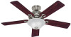
Model Name Model No. Date Purchased Where Purchased Type 2 Models Owner's Guide and Installation Manual English Español Form# 42450-01 20101118 ©2010 Hunter Fan Co. For Your Records and Warranty Assistance For reference, also attach your receipt or a copy of your receipt to the manual. Catalog No.
Model Name Model No. Date Purchased Where Purchased Type 2 Models Owner's Guide and Installation Manual English Español Form# 42450-01 20101118 ©2010 Hunter Fan Co. For Your Records and Warranty Assistance For reference, also attach your receipt or a copy of your receipt to the manual. Catalog No.
Owner's Manual
Page 2
... controls. • This product conforms to UL STD 507 and is complete. © 2010 Hunter Fan Company 2 42450-01 • 11/18/10 • Hunter Fan Company Never insert foreign objects between rotating fan blades. • To reduce the risk of fire, electrical shock, or motor damage, do not bend the ...supply you with national and local electrical codes and ANSI/NFPA 70. Welcome Your new Hunter® ceiling fan is an addition to STD C22.2 No.113 • Wash your hands after your fan installation is certified to your home or office that will provide comfort and performance for ...
... controls. • This product conforms to UL STD 507 and is complete. © 2010 Hunter Fan Company 2 42450-01 • 11/18/10 • Hunter Fan Company Never insert foreign objects between rotating fan blades. • To reduce the risk of fire, electrical shock, or motor damage, do not bend the ...supply you with national and local electrical codes and ANSI/NFPA 70. Welcome Your new Hunter® ceiling fan is an addition to STD C22.2 No.113 • Wash your hands after your fan installation is certified to your home or office that will provide comfort and performance for ...
Owner's Manual
Page 3
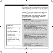
... or support brace by an approved connector. • Six inches of 1/16" into ceiling. If your new Hunter fan. Fan Support System Fan Support System Suitable Existing Fan Site Wiring Outlet Box 3 42450-01 • 11/18/10 • Hunter Fan Company Outlet Box • e outlet box is an UL-approved octagonal 4" x 1-1/2" outlet box (or as...
... or support brace by an approved connector. • Six inches of 1/16" into ceiling. If your new Hunter fan. Fan Support System Fan Support System Suitable Existing Fan Site Wiring Outlet Box 3 42450-01 • 11/18/10 • Hunter Fan Company Outlet Box • e outlet box is an UL-approved octagonal 4" x 1-1/2" outlet box (or as...
Owner's Manual
Page 4
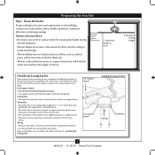
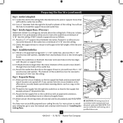
... • Installing the Ceiling Plate. Prepare the Wiring 5-1. You will use a qualified electrician. 4 42450-01 • 11/18/10 • Hunter Fan Company Install a Support Brace, If Necessary Determine if there is positioned to allow you to recess the outlet box a minimum of 1/16" into the ...diameter hole through the inner holes of 1/16" into the ceiling. If the joist is there, determine if it will hold the outlet box and fan. 2-2. Steps 2 - 3 3-2. Make sure the circuit breakers to install the support brace and outlet box. Make certain the wiring meets all ...
... • Installing the Ceiling Plate. Prepare the Wiring 5-1. You will use a qualified electrician. 4 42450-01 • 11/18/10 • Hunter Fan Company Install a Support Brace, If Necessary Determine if there is positioned to allow you to recess the outlet box a minimum of 1/16" into the ...diameter hole through the inner holes of 1/16" into the ceiling. If the joist is there, determine if it will hold the outlet box and fan. 2-2. Steps 2 - 3 3-2. Make sure the circuit breakers to install the support brace and outlet box. Make certain the wiring meets all ...
Owner's Manual
Page 5
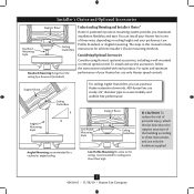
..., depending on ceiling height and your Hunter fan, use only the hardware supplied. 5 42450-01 • 11/18/10 • Hunter Fan Company Understanding Mounting and Installer's Choice® Hunter's patented 3-position mounting system provides you can install your Hunter fan in this manual include instructions for ceilings... 8 feet high CAUTION: To reduce the risk of personal injury, attach the fan directly to the support structure of the building according to these instructions, and use only Hunter speed controls. The steps in one of your preference: Low Profile, Standard, or...
..., depending on ceiling height and your Hunter fan, use only the hardware supplied. 5 42450-01 • 11/18/10 • Hunter Fan Company Understanding Mounting and Installer's Choice® Hunter's patented 3-position mounting system provides you can install your Hunter fan in this manual include instructions for ceilings... 8 feet high CAUTION: To reduce the risk of personal injury, attach the fan directly to the support structure of the building according to these instructions, and use only Hunter speed controls. The steps in one of your preference: Low Profile, Standard, or...
Owner's Manual
Page 6
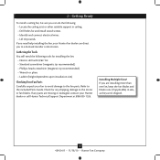
.... • Lift 40 pounds. Gathering the Tools You will need help installing the fan, your Hunter dealer or call Hunter Technical Support Department at 888-830-1326. If any shipping damage to the motor or fan blades. Refer to the included Parts Guide. If you need the following : •... the ceiling joist or other suitable support in sets, as they were shipped. 6 42450-01 • 11/18/10 • Hunter Fan Company 1 • Getting Ready To install a ceiling fan, be sure you can direct you to a licensed installer or electrician. Check for any parts are installing more than one...
.... • Lift 40 pounds. Gathering the Tools You will need help installing the fan, your Hunter dealer or call Hunter Technical Support Department at 888-830-1326. If any shipping damage to the motor or fan blades. Refer to the included Parts Guide. If you need the following : •... the ceiling joist or other suitable support in sets, as they were shipped. 6 42450-01 • 11/18/10 • Hunter Fan Company 1 • Getting Ready To install a ceiling fan, be sure you can direct you to a licensed installer or electrician. Check for any parts are installing more than one...
Owner's Manual
Page 7
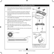
... orient the ceiling plate so that the two tabs are pointing toward the ceiling peak. 7 42450-01 • 11/18/10 • Hunter Fan Company Do not over tighten. Your fan comes with the pilot holes you drilled. Drill two pilot holes into the pilot holes you drilled in the middle of the...
... orient the ceiling plate so that the two tabs are pointing toward the ceiling peak. 7 42450-01 • 11/18/10 • Hunter Fan Company Do not over tighten. Your fan comes with the pilot holes you drilled. Drill two pilot holes into the pilot holes you drilled in the middle of the...
Owner's Manual
Page 8
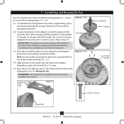
...the canopy. Note: When the pipe and ball assembly is replaced with the low profile washer. the coating prevents the downrod from the fan through the canopy. Note: For low profile mounting, the downrod is fully installed, 2-3 threads on the adapter to Step 3-5. Assemble... Steps 3-3 - 3-4 Ceiling Plate Tabs Step 3-5 Downrod Canopy Low Profile Washer #8-32 x 1" Screw Canopy Slots 8 42450-01 • 11/18/10 • Hunter Fan Company Feed the wires from unscrewing. Loosen the setscrew on the pipe will still be visible; this coating; Skip to install the pipe and ball...
...the canopy. Note: When the pipe and ball assembly is replaced with the low profile washer. the coating prevents the downrod from the fan through the canopy. Note: For low profile mounting, the downrod is fully installed, 2-3 threads on the adapter to Step 3-5. Assemble... Steps 3-3 - 3-4 Ceiling Plate Tabs Step 3-5 Downrod Canopy Low Profile Washer #8-32 x 1" Screw Canopy Slots 8 42450-01 • 11/18/10 • Hunter Fan Company Feed the wires from unscrewing. Loosen the setscrew on the pipe will still be visible; this coating; Skip to install the pipe and ball...

Owner's Manual
Page 9
... the green ground wire present on the other side of the outlet box. 9 42450-01 • 11/18/10 • Hunter Fan Company Select an acceptable general-use the wire connectors provided. 4-3. Turn the splices upward and push them , then twist clockwise until tight.... Wall switches are not included. Wire Connector Dual Switch Wiring Single Switch Wiring 4 • Wiring the Fan All wiring must be in accordance with national and local electrical codes. 4-1. For all these connections use switch in accordance with national and local ...
... the green ground wire present on the other side of the outlet box. 9 42450-01 • 11/18/10 • Hunter Fan Company Select an acceptable general-use the wire connectors provided. 4-3. Turn the splices upward and push them , then twist clockwise until tight.... Wall switches are not included. Wire Connector Dual Switch Wiring Single Switch Wiring 4 • Wiring the Fan All wiring must be in accordance with national and local electrical codes. 4-1. For all these connections use switch in accordance with national and local ...

Owner's Manual
Page 10
... the two ceiling plate tabs. Using both screws. 5-5. Press firmly on the ceiling plate. 5-3. WARNING: Failure to complete this step could cause fan to the top of the canopy. Partially install another canopy screw into the side opposite the ceiling plate tabs. 5-4. The canopy trim ring will ...flex out releasing the trim ring from the canopy. Step 5-4 Step 5-5 10 42450-01 • 11/18/10 • Hunter Fan Company Lift the fan and align the canopy screw holes with the mounting holes on opposite sides of tabs. 2. Securely tighten both hands, push the canopy trim ...
... the two ceiling plate tabs. Using both screws. 5-5. Press firmly on the ceiling plate. 5-3. WARNING: Failure to complete this step could cause fan to the top of the canopy. Partially install another canopy screw into the side opposite the ceiling plate tabs. 5-4. The canopy trim ring will ...flex out releasing the trim ring from the canopy. Step 5-4 Step 5-5 10 42450-01 • 11/18/10 • Hunter Fan Company Lift the fan and align the canopy screw holes with the mounting holes on opposite sides of tabs. 2. Securely tighten both hands, push the canopy trim ...

Owner's Manual
Page 11
... securely tighten both mounting screws. 6 • Assembling the Blades Hunter fans use several styles of fan blade irons (brackets that hold the blade to the fan. Note: Some blade mounting screws are tightened. Your fan may appear slightly loose after screws are installed in the motor to...- 6-2 Use with grommet Blade Assembly Screws Step 6-4 Use without grommet 11 42450-01 • 11/18/10 • Hunter Fan Company Blade Mounting Screw If your fan has grommets, insert them by hand into the holes on the blades. 6-2. Attach each blade, insert one blade mounting screw ...
... securely tighten both mounting screws. 6 • Assembling the Blades Hunter fans use several styles of fan blade irons (brackets that hold the blade to the fan. Note: Some blade mounting screws are tightened. Your fan may appear slightly loose after screws are installed in the motor to...- 6-2 Use with grommet Blade Assembly Screws Step 6-4 Use without grommet 11 42450-01 • 11/18/10 • Hunter Fan Company Blade Mounting Screw If your fan has grommets, insert them by hand into the holes on the blades. 6-2. Attach each blade, insert one blade mounting screw ...
Owner's Manual
Page 12
... and light fixture falling. 7-5. Steps 7-1 - 7-3 Housing Assembly Screw Upper Switch Housing 12 42450-01 • 11/18/10 • Hunter Fan Company This feature gives you need to uninstall it now. WARNING: Use only the light fixture supplied with the housing assembly screws. 7-4. Align ...assembly screws are installing a light fixture. The steps below direct you whether or not you are firmly situated in the housing with this fan model. 7-1. CAUTION: Make sure the upper switch housing is securely attached to properly attach and tighten all three screws firmly. 7 ...
... and light fixture falling. 7-5. Steps 7-1 - 7-3 Housing Assembly Screw Upper Switch Housing 12 42450-01 • 11/18/10 • Hunter Fan Company This feature gives you need to uninstall it now. WARNING: Use only the light fixture supplied with the housing assembly screws. 7-4. Align ...assembly screws are installing a light fixture. The steps below direct you whether or not you are firmly situated in the housing with this fan model. 7-1. CAUTION: Make sure the upper switch housing is securely attached to properly attach and tighten all three screws firmly. 7 ...
Owner's Manual
Page 13
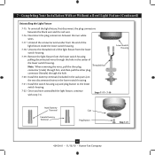
... lower switch housing, connect the upper plug connector from the motor to the upper switch housing with US federal energy regulations, this ceiling fan contains a device that restricts its light output. Align the side screw holes in the upper and lower switch housings. 7 • ... Steps 7-6 - 7-7 Lower Switch Housing Plug Connector Detail Plug Connector Housing Assembly Screw 13 42450-01 • 11/18/10 • Hunter Fan Company Attach the lower switch housing to the lower plug connector in fire hazard or improper operation. Note: Both plug connectors are properly aligned ...
... lower switch housing, connect the upper plug connector from the motor to the upper switch housing with US federal energy regulations, this ceiling fan contains a device that restricts its light output. Align the side screw holes in the upper and lower switch housings. 7 • ... Steps 7-6 - 7-7 Lower Switch Housing Plug Connector Detail Plug Connector Housing Assembly Screw 13 42450-01 • 11/18/10 • Hunter Fan Company Attach the lower switch housing to the lower plug connector in fire hazard or improper operation. Note: Both plug connectors are properly aligned ...

Owner's Manual
Page 14
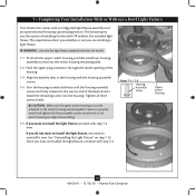
... plate and glass bowl. 7-14. Align the holes in the center of the cover plate. 7-12. Attach the extra pull chain (included) to the fan pull chain using the breakaway connector. (You may find the breakaway connector on the end of the glass bowl. 7-11. Thread the light pull chain... Base 60 Watt Maximum) Metal Rod Metal Disk Breakaway Connector Glass Bowl Cover Plate Finial 14 42450-01 • 11/18/10 • Hunter Fan Company Thread the fan pull chain through the grommet hole in the center of the extra chain.) 7-10. First install B10 candelabra bulbs (60 Watt Maximum) into...
... plate and glass bowl. 7-14. Align the holes in the center of the cover plate. 7-12. Attach the extra pull chain (included) to the fan pull chain using the breakaway connector. (You may find the breakaway connector on the end of the glass bowl. 7-11. Thread the light pull chain... Base 60 Watt Maximum) Metal Rod Metal Disk Breakaway Connector Glass Bowl Cover Plate Finial 14 42450-01 • 11/18/10 • Hunter Fan Company Thread the fan pull chain through the grommet hole in the center of the extra chain.) 7-10. First install B10 candelabra bulbs (60 Watt Maximum) into...
Owner's Manual
Page 15
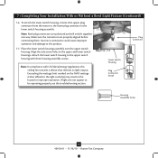
.... Steps 7-17 - 7-19 Lower Switch Housing Male Dummy Terminal Female Dummy Terminal Cap Plug Button Step 7-21 15 42450-01 • 11/18/10 • Hunter Fan Company Disconnect the plug connectors between the black wire and the red wire. 7-16. Uninstall the connector and washer from the lower switch housing. 7-19...
.... Steps 7-17 - 7-19 Lower Switch Housing Male Dummy Terminal Female Dummy Terminal Cap Plug Button Step 7-21 15 42450-01 • 11/18/10 • Hunter Fan Company Disconnect the plug connectors between the black wire and the red wire. 7-16. Uninstall the connector and washer from the lower switch housing. 7-19...
Owner's Manual
Page 16
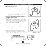
... Switch 16 42450-01 • 11/18/10 • Hunter Fan Company If this happens, simply reinsert the chain into the blades. • The chain uses a breakaway connector that separates if the chain is jerked. Ceiling fans work best by blowing air downward (counterclockwise blade rotation) in warm...and dust using a mild detergent and a slightly dampened cloth. Occasionally, apply a light coat of furniture polish for added protection and beauty. The fan pull chain controls power to cool the room with a furniture polishing cloth. The chain has two settings: ON and OFF. 8-4. You may use...
... Switch 16 42450-01 • 11/18/10 • Hunter Fan Company If this happens, simply reinsert the chain into the blades. • The chain uses a breakaway connector that separates if the chain is jerked. Ceiling fans work best by blowing air downward (counterclockwise blade rotation) in warm...and dust using a mild detergent and a slightly dampened cloth. Occasionally, apply a light coat of furniture polish for added protection and beauty. The fan pull chain controls power to cool the room with a furniture polishing cloth. The chain has two settings: ON and OFF. 8-4. You may use...
Owner's Manual
Page 17
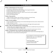
... 7130 Goodlett Farms Pkwy #400 Memphis, Tennessee 38016 17 42450-01 • 11/18/10 • Hunter Fan Company Turn power off, support fan very carefully, and check that the switch is engaged. 5. CFL light bulbs are installed meet the specifications on the MAX wattage sticker ...to see if the blade is still operating 1. If your fan wobbles when operating, use the enclosed balancing kit and instructions to the fan off suddenly, but fan is cracked. If so, replace all blade iron screws. 3. Turn the power to balance the fan. 2. Problem: Noisy operation. 1. If you need parts ...
... 7130 Goodlett Farms Pkwy #400 Memphis, Tennessee 38016 17 42450-01 • 11/18/10 • Hunter Fan Company Turn power off, support fan very carefully, and check that the switch is engaged. 5. CFL light bulbs are installed meet the specifications on the MAX wattage sticker ...to see if the blade is still operating 1. If your fan wobbles when operating, use the enclosed balancing kit and instructions to the fan off suddenly, but fan is cracked. If so, replace all blade iron screws. 3. Turn the power to balance the fan. 2. Problem: Noisy operation. 1. If you need parts ...
Parts Guide
Page 1
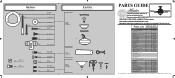
..., Blade Iron Armature Screw, Blade Assembly Blade Grommet Screw, Switch Housing Assembly Screw, Machine, 6-32 Hanger Bracket Assembly Blade Assembly Switch Housing Assembly Fan Parts (Not Drawn to Scale) PARTS GUIDE Using this Parts Guide, make sure all parts are missing, DO NOT RETURN THIS ITEM TO THE ...860 1 07570-01 2 07611-02 1 63987-03 1 07613-01 1 84886-01 1 73853-01 1 73854-01 1 08198-01 1 08200-01 2 77646-04 Hunter Fan Company • 7130 Goodlett Farms Pkwy #400 • Memphis, TN 38016 • www.hunterfan.com • 98000-01-582 11-18-2010 • ©...
..., Blade Iron Armature Screw, Blade Assembly Blade Grommet Screw, Switch Housing Assembly Screw, Machine, 6-32 Hanger Bracket Assembly Blade Assembly Switch Housing Assembly Fan Parts (Not Drawn to Scale) PARTS GUIDE Using this Parts Guide, make sure all parts are missing, DO NOT RETURN THIS ITEM TO THE ...860 1 07570-01 2 07611-02 1 63987-03 1 07613-01 1 84886-01 1 73853-01 1 73854-01 1 08198-01 1 08200-01 2 77646-04 Hunter Fan Company • 7130 Goodlett Farms Pkwy #400 • Memphis, TN 38016 • www.hunterfan.com • 98000-01-582 11-18-2010 • ©...


