
Operation Guide
Page 4
Table Of Contents System Communication and Operation ...3-1 Panel Communication with Central Station ...3-1 Report Code Formats...3-1 Ademco Contact ID® ...3-3 Uploading/Downloading via the Internet ...3-4 System Security Codes ...3-5 Panic Keys...3-7 Setting the Real-Time Clock ...3-7 Various System Trouble Displays ...3-8 Testing the ... ...4-2 Dialer Communication Test and Periodic Test Reports 4-2 Automatic Standby Battery Tests...4-2 Specifications & Accessories...5-1 Security Control...5-1 Compatible Devices ...5-1 Regulatory Agency Statements ...6-1 Limitations and Warranty ...7-3 iv
Table Of Contents System Communication and Operation ...3-1 Panel Communication with Central Station ...3-1 Report Code Formats...3-1 Ademco Contact ID® ...3-3 Uploading/Downloading via the Internet ...3-4 System Security Codes ...3-5 Panic Keys...3-7 Setting the Real-Time Clock ...3-7 Various System Trouble Displays ...3-8 Testing the ... ...4-2 Dialer Communication Test and Periodic Test Reports 4-2 Automatic Standby Battery Tests...4-2 Specifications & Accessories...5-1 Security Control...5-1 Compatible Devices ...5-1 Regulatory Agency Statements ...6-1 Limitations and Warranty ...7-3 iv
Operation Guide
Page 9
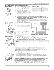
... transformer into the AC outlet until all connections to guard against blowing the transformer fuse (the fuse is restored. This assists the control panel in recharging the battery when AC is non-replaceable). You must not exceed 250 feet using Powerline Carrier devices) AC AC OSuytnpcut ... lightning and electrical discharge, and does not normally require an earth ground. • If an earth ground is electrically connected and secured. The following are complete. See Wire Run Chart for additional protection in areas of Connections diagram for connections to meet the mandatory ...
... transformer into the AC outlet until all connections to guard against blowing the transformer fuse (the fuse is restored. This assists the control panel in recharging the battery when AC is non-replaceable). You must not exceed 250 feet using Powerline Carrier devices) AC AC OSuytnpcut ... lightning and electrical discharge, and does not normally require an earth ground. • If an earth ground is electrically connected and secured. The following are complete. See Wire Run Chart for additional protection in areas of Connections diagram for connections to meet the mandatory ...
Operation Guide
Page 14
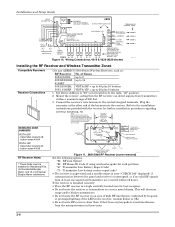
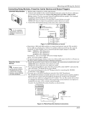
Installation and Setup Guide WHT GRY VIO BLK YEL ORG BRN RELAY CONNECTOR RELAY 2 DIP SWITCH FOR SETTING ADDRESS AND ZONE "A" RESPONSE RELAY 1 NO C NC TAMPER JUMPER POSITION 4229 IN CABINET (NOT TAMPER) 4229 REMOTE (TAMPER PROTECTED) 12 3456 78 4229 EITHER OR BOTH CAN BE USED TERMINALS ON CONTROL PANEL 4-PIN CONSOLE PLUG TB2 4 TB1 9 10 11 12 3 4 3 22 11 GRN DATA OUT (>) TO CONTROL BLK (-) GROUND RED (+) 12VDC YEL DATA IN (
Installation and Setup Guide WHT GRY VIO BLK YEL ORG BRN RELAY CONNECTOR RELAY 2 DIP SWITCH FOR SETTING ADDRESS AND ZONE "A" RESPONSE RELAY 1 NO C NC TAMPER JUMPER POSITION 4229 IN CABINET (NOT TAMPER) 4229 REMOTE (TAMPER PROTECTED) 12 3456 78 4229 EITHER OR BOTH CAN BE USED TERMINALS ON CONTROL PANEL 4-PIN CONSOLE PLUG TB2 4 TB1 9 10 11 12 3 4 3 22 11 GRN DATA OUT (>) TO CONTROL BLK (-) GROUND RED (+) 12VDC YEL DATA IN (
Operation Guide
Page 15
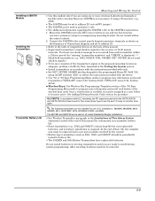
Connect the 5800TM to the control panel's keypad connection terminals as 5801, ...• For additional information regarding the 5800TM, refer to program zone information and enroll transmitters (VISTA-20P: zones 9-48, buttons 49-64; See Adding/Deleting Security Codes section for battery life. • The 5802MN and 5804...VISTA-20PCN and VISTA-15PCN is required. VISTA-15P: zones 9-34, buttons 49-56). • Wireless Keys: Use Wireless Key Programming Templates section of the *58 Zone Programming Menu mode to program zone information and enroll each transmitter within the control...
Connect the 5800TM to the control panel's keypad connection terminals as 5801, ...• For additional information regarding the 5800TM, refer to program zone information and enroll transmitters (VISTA-20P: zones 9-48, buttons 49-64; See Adding/Deleting Security Codes section for battery life. • The 5802MN and 5804...VISTA-20PCN and VISTA-15PCN is required. VISTA-15P: zones 9-34, buttons 49-56). • Wireless Keys: Use Wireless Key Programming Templates section of the *58 Zone Programming Menu mode to program zone information and enroll each transmitter within the control...
Operation Guide
Page 17
...The module's device address is displayed as follows if a module is disconnected from the control panel through the premises AC wiring to the Powerline Carrier devices (which are used ) VISTA-15P: Up to commands you enter at the security system keypads. BLACK 2 - YELLOW Figure 14. Connect each . UL For UL ... cover is removed and the tamper jumper is the module's address. • If communication/tamper failure occurs on a device with zones wired to the control's keypad terminals and set for 2-digit display) where "xx is installed: Alpha: CHECK xx Wire Expansion FAULT xx Wire Expansion ...
...The module's device address is displayed as follows if a module is disconnected from the control panel through the premises AC wiring to the Powerline Carrier devices (which are used ) VISTA-15P: Up to commands you enter at the security system keypads. BLACK 2 - YELLOW Figure 14. Connect each . UL For UL ... cover is removed and the tamper jumper is the module's address. • If communication/tamper failure occurs on a device with zones wired to the control's keypad terminals and set for 2-digit display) where "xx is installed: Alpha: CHECK xx Wire Expansion FAULT xx Wire Expansion ...
Operation Guide
Page 19
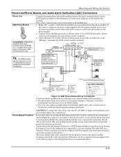
...to access the system from an on-premises phone. • If you are produced following access to the security system from the phone module to terminals (21) & (22) on the control. RING PHONE INPUT } 3 - CAUTION: To reduce the risk of the connector cable into the header... OUT (term. 7) NO CONNECTION RED: TO AUX (+) (term. 5) BLACK: TO AUX. GROUND (-) (term.4) GREEN: TO DATA IN (term. 6) TO CONTROL PANEL TERMINALS USED FOR KEYPAD CONNECTIONS 4286 TERMINAL ASSIGNMENTS } 1 - The wiring diagram shows the wiring connections that will occur when trying to the RJ31X jack. 1.
...to access the system from an on-premises phone. • If you are produced following access to the security system from the phone module to terminals (21) & (22) on the control. RING PHONE INPUT } 3 - CAUTION: To reduce the risk of the connector cable into the header... OUT (term. 7) NO CONNECTION RED: TO AUX (+) (term. 5) BLACK: TO AUX. GROUND (-) (term.4) GREEN: TO DATA IN (term. 6) TO CONTROL PANEL TERMINALS USED FOR KEYPAD CONNECTIONS 4286 TERMINAL ASSIGNMENTS } 1 - The wiring diagram shows the wiring connections that will occur when trying to the RJ31X jack. 1.
Operation Guide
Page 21
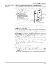
...As shipped, the AVS Base unit board comes pre-mounted on the next page for 2-way voice operation, install the module according to the control panel. b. TANG BENEATH MOUNTING PLATE SLIDE ASSEMBLY TO RIGHT UNTIL TANG SLIPS UNDER CABINET LOOP AVS-003-V0 BATTERY NOTE: When using a 7AH... programming steps for making connections to remote stations, telephone lines, and to its mounting bracket, which is a summary. Position the mounting plate/PC SECURE WITH TWO (2) SELF-TAP SCREWS (SUPPLIED) board assembly in the bottom of the AVS Quick Command options): a. V20P = 11). If using ...
...As shipped, the AVS Base unit board comes pre-mounted on the next page for 2-way voice operation, install the module according to the control panel. b. TANG BENEATH MOUNTING PLATE SLIDE ASSEMBLY TO RIGHT UNTIL TANG SLIPS UNDER CABINET LOOP AVS-003-V0 BATTERY NOTE: When using a 7AH... programming steps for making connections to remote stations, telephone lines, and to its mounting bracket, which is a summary. Position the mounting plate/PC SECURE WITH TWO (2) SELF-TAP SCREWS (SUPPLIED) board assembly in the bottom of the AVS Quick Command options): a. V20P = 11). If using ...


