

User Guide
Page 10
... arming (due to open is ready to arm when this message disappears and the READY indicator light comes on backup battery power. Appears when a fire alarm is activated. Appears when burglary portion of the zone in a DAY/NIGHT burglary zone during a fire alarm or audible emergency alarm). The system is detected in a fire...
... arming (due to open is ready to arm when this message disappears and the READY indicator light comes on backup battery power. Appears when a fire alarm is activated. Appears when burglary portion of the zone in a DAY/NIGHT burglary zone during a fire alarm or audible emergency alarm). The system is detected in a fire...

User Guide
Page 40
... Alarm Global Trouble, Trouble Day/Night RF Supervision Trouble Supervision Auxiliary Wire Zone RF Sensor Tamper RF Sensor Low-battery Clean Me Code 401 403 406 407 408 409 441 442 459 570... Entry (log only) Program Mode Exit (log only) Latch Key (log only) Reserved for Configurable Zone Type report codes (check with central station when using these codes) NOTE: Ask your installer to explain...Silent Burglary Alarm, 24-Hour Auxiliary/Monitor zone Carbon Monoxide AC Power Low System Battery/Battery Test Fail System Reset (Log only) Battery Test Failure Bell/Siren Trouble Trouble, Expansion Mod.
... Alarm Global Trouble, Trouble Day/Night RF Supervision Trouble Supervision Auxiliary Wire Zone RF Sensor Tamper RF Sensor Low-battery Clean Me Code 401 403 406 407 408 409 441 442 459 570... Entry (log only) Program Mode Exit (log only) Latch Key (log only) Reserved for Configurable Zone Type report codes (check with central station when using these codes) NOTE: Ask your installer to explain...Silent Burglary Alarm, 24-Hour Auxiliary/Monitor zone Carbon Monoxide AC Power Low System Battery/Battery Test Fail System Reset (Log only) Battery Test Failure Bell/Siren Trouble Trouble, Expansion Mod.

User Guide
Page 41
...the detector should appear on the display when it is inadvertently left active, it automatically turns off . The display clears when no zone identification numbers displayed on the keypad. 7. Test all protected windows, Alpha Displays: doors, etc. If a problem is intended for ... of each detector should be checked for three beeps from the keypad. Fault zones. The identification of each protection point to be conducted weekly to your Security System Representative. 3. This conserves battery life. 6. Testing should appear on the display when each protected door and ...
...the detector should appear on the display when it is inadvertently left active, it automatically turns off . The display clears when no zone identification numbers displayed on the keypad. 7. Test all protected windows, Alpha Displays: doors, etc. If a problem is intended for ... of each detector should be checked for three beeps from the keypad. Fault zones. The identification of each protection point to be conducted weekly to your Security System Representative. 3. This conserves battery life. 6. Testing should appear on the display when each protected door and ...

User Guide
Page 42
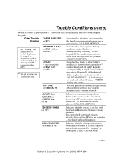
...), and you enter the OFF sequence (security code plus OFF key) twice. See "BELL FAILURE" on next page. 2. Determine if the zone(s) displayed are intact and make them so if they are wireless sensors* in your attention. TYPICAL "CHECK" DISPLAYS 06 AC CHECK FIXED-WORD ...zone(s) and requires your system, the CHECK condition may also be cleared if you should CALL FOR SERVICE. CALL FOR SERVICE if this occurs. * Not all systems use wireless sensors. See "Rcvr Jam" on next page. IF YOU CANNOT CORRECT A "CHECK" DISPLAY, CALL FOR SERVICE. Trouble Conditions "Check" and "Battery...
...), and you enter the OFF sequence (security code plus OFF key) twice. See "BELL FAILURE" on next page. 2. Determine if the zone(s) displayed are intact and make them so if they are wireless sensors* in your attention. TYPICAL "CHECK" DISPLAYS 06 AC CHECK FIXED-WORD ...zone(s) and requires your system, the CHECK condition may also be cleared if you should CALL FOR SERVICE. CALL FOR SERVICE if this occurs. * Not all systems use wireless sensors. See "Rcvr Jam" on next page. IF YOU CANNOT CORRECT A "CHECK" DISPLAY, CALL FOR SERVICE. Trouble Conditions "Check" and "Battery...
User Guide
Page 43
... Displays (or FC) * Any "beeping" that the control is on Fixed-Word Display keypads. SYSTEM LO BAT (or BAT with no zone No.) LO BAT + zone descriptor (or BAT with AC present), CALL FOR SERVICE. Either replace the battery yourself, or CALL FOR SERVICE. Accompanied by a single ... (open or shorted). If the battery is not replaced within 30 days, a CHECK display may impede reception from wireless sensors.** ALARM 1xx FAULT 1xx CHECK 1xx (or 91) Indicates a communication problem between the control and a connected device (e.g., RF receiver, zone expander) where the "xx" indicates...
... Displays (or FC) * Any "beeping" that the control is on Fixed-Word Display keypads. SYSTEM LO BAT (or BAT with no zone No.) LO BAT + zone descriptor (or BAT with AC present), CALL FOR SERVICE. Either replace the battery yourself, or CALL FOR SERVICE. Accompanied by a single ... (open or shorted). If the battery is not replaced within 30 days, a CHECK display may impede reception from wireless sensors.** ALARM 1xx FAULT 1xx CHECK 1xx (or 91) Indicates a communication problem between the control and a connected device (e.g., RF receiver, zone expander) where the "xx" indicates...

User Guide
Page 44
...your installer demonstrate this message remains displayed for information on installation of your system, back-up battery) for service. CALL FOR SERVICE. If part of telephone operational problems, disconnect the control from the phone line by authorized service (see previous page), CALL FOR SERVICE. In .... CALL FOR SERVICE. If AC power cannot be made only by removing the plug from the control. If upon disconnection of the control, there is disabled. If only some lights are out on battery power only due to obtain service). - 44 - The telephone line has a problem.
...your installer demonstrate this message remains displayed for information on installation of your system, back-up battery) for service. CALL FOR SERVICE. If part of telephone operational problems, disconnect the control from the phone line by authorized service (see previous page), CALL FOR SERVICE. In .... CALL FOR SERVICE. If AC power cannot be made only by removing the plug from the control. If upon disconnection of the control, there is disabled. If only some lights are out on battery power only due to obtain service). - 44 - The telephone line has a problem.

User Guide
Page 45
When you replace the weak battery with a fresh one, the sensor sends a "good battery" signal to the control as soon as the sensor is activated (opening/closing of door, window, etc.), causing the low battery display to 4 or more of your wireless sensors. Each wireless sensor in your system weekly. 2. Routine ...and the specific type of sensor. Factors such as humidity, high or low temperatures or large swings in temperature, may not have a low battery condition in one of its keys is not activated, the display will remain on as a reminder that you would any other fluid on ...
When you replace the weak battery with a fresh one, the sensor sends a "good battery" signal to the control as soon as the sensor is activated (opening/closing of door, window, etc.), causing the low battery display to 4 or more of your wireless sensors. Each wireless sensor in your system weekly. 2. Routine ...and the specific type of sensor. Factors such as humidity, high or low temperatures or large swings in temperature, may not have a low battery condition in one of its keys is not activated, the display will remain on as a reminder that you would any other fluid on ...

User Guide
Page 51
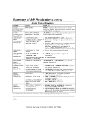
... MINUTES ARM AWAY or MAXIMUM a. SOUNDER WIRING FAIL a. zone number of open protection zone displayed. Zone numbers of zone in alarm is displayed; a. Opened zone numbers will be displayed. c. b. AWAY is displayed. LOW BATTERY AT A TRANSMITTER c. EXT. EXIT DELAY WARNING b. c. a. BAT displayed with zone number of the open protection zone will appear. CHECK 70 is displayed. burglary/audible...
... MINUTES ARM AWAY or MAXIMUM a. SOUNDER WIRING FAIL a. zone number of open protection zone displayed. Zone numbers of zone in alarm is displayed; a. Opened zone numbers will be displayed. c. b. AWAY is displayed. LOW BATTERY AT A TRANSMITTER c. EXT. EXIT DELAY WARNING b. c. a. BAT displayed with zone number of the open protection zone will appear. CHECK 70 is displayed. burglary/audible...
User Guide
Page 52
... b. ENTRY DELAY WARNING. b. descriptor of transmitter. BELL FAILURE is displayed; ARMED AWAY or MAXIMUM is displayed along with description of zone in alarm is displayed. FIRE is displayed. LOUD, BURGLARY/AUDIBLE CONTINUOUS* EMERGENCY ALARM. Keypad & Ext. ALARM is displayed. DISARMED/READY...LOUD, FIRE ALARM. SYSTEM IS IN TEST MODE. a. a. Summary of the bypassed zones are displayed (One beep is heard for each zone displayed). b, LOW BATTERY AT A TRANSMITTER. b. SYSTEM LOW BATTERY. DISARM SYSTEM OR ALARM WILL OCCUR is steady ring. - 52 - burglary/audible...
... b. ENTRY DELAY WARNING. b. descriptor of transmitter. BELL FAILURE is displayed; ARMED AWAY or MAXIMUM is displayed along with description of zone in alarm is displayed. FIRE is displayed. LOUD, BURGLARY/AUDIBLE CONTINUOUS* EMERGENCY ALARM. Keypad & Ext. ALARM is displayed. DISARMED/READY...LOUD, FIRE ALARM. SYSTEM IS IN TEST MODE. a. a. Summary of the bypassed zones are displayed (One beep is heard for each zone displayed). b, LOW BATTERY AT A TRANSMITTER. b. SYSTEM LOW BATTERY. DISARM SYSTEM OR ALARM WILL OCCUR is steady ring. - 52 - burglary/audible...

User Guide
Page 63
...another level of alarm systems owe it does not offer guaranteed protection against burglary or other sensing devices will not work without batteries, with this system is subject to compromise or failure to develop new and improved protection devices. Users of a residence or... and continue to insure their loved ones to component failure. passive infrared detectors), smoke detectors, and many as diagrammed in temperature; Battery operated devices will not work are working properly. We continue to warn for example, may not respond appropriately. • This equipment...
...another level of alarm systems owe it does not offer guaranteed protection against burglary or other sensing devices will not work without batteries, with this system is subject to compromise or failure to develop new and improved protection devices. Users of a residence or... and continue to insure their loved ones to component failure. passive infrared detectors), smoke detectors, and many as diagrammed in temperature; Battery operated devices will not work are working properly. We continue to warn for example, may not respond appropriately. • This equipment...

Operation Guide
Page 3
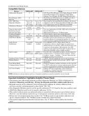
... Installation Highlights (Installer Please Read 1-2 Mounting and Wiring the Control ...2-1 Installing the Control Cabinet and PC Board ...2-1 Cabinet and Lock ...2-1 Mounting the...Zones and Zone Expansion ...2-6 Hardwire Zones ...2-6 Double-Balanced Zones...2-6 Zone Doubling ...2-6 Smoke Detectors...2-6 Smoke Detector Notes...2-7 4219/4229 Expansion Zones ...2-7 Installing the RF Receiver and Wireless Transmitter Zones 2-8 Compatible Receivers...2-8 Receiver Connections ...2-8 RF Receiver Notes...2-8 Installing a 5800TM Module ...2-9 Installing the Transmitters ...2-9 Transmitter Battery...
... Installation Highlights (Installer Please Read 1-2 Mounting and Wiring the Control ...2-1 Installing the Control Cabinet and PC Board ...2-1 Cabinet and Lock ...2-1 Mounting the...Zones and Zone Expansion ...2-6 Hardwire Zones ...2-6 Double-Balanced Zones...2-6 Zone Doubling ...2-6 Smoke Detectors...2-6 Smoke Detector Notes...2-7 4219/4229 Expansion Zones ...2-7 Installing the RF Receiver and Wireless Transmitter Zones 2-8 Compatible Receivers...2-8 Receiver Connections ...2-8 RF Receiver Notes...2-8 Installing a 5800TM Module ...2-9 Installing the Transmitters ...2-9 Transmitter Battery...

Operation Guide
Page 4
Table Of Contents System Communication and Operation ...3-1 Panel Communication with Central Station ...3-1 Report Code Formats...3-1 Ademco Contact ID® ...3-3 Uploading/Downloading via the Internet ...3-4 System Security Codes ...3-5 Panic Keys...3-7 Setting the Real-Time Clock ... Enrollment (Sniffer Mode)...4-1 Go/No Go Test Mode ...4-2 Dialer Communication Test and Periodic Test Reports 4-2 Automatic Standby Battery Tests...4-2 Specifications & Accessories...5-1 Security Control...5-1 Compatible Devices ...5-1 Regulatory Agency Statements ...6-1 Limitations and Warranty ...7-3 iv
Table Of Contents System Communication and Operation ...3-1 Panel Communication with Central Station ...3-1 Report Code Formats...3-1 Ademco Contact ID® ...3-3 Uploading/Downloading via the Internet ...3-4 System Security Codes ...3-5 Panic Keys...3-7 Setting the Real-Time Clock ... Enrollment (Sniffer Mode)...4-1 Go/No Go Test Mode ...4-2 Dialer Communication Test and Periodic Test Reports 4-2 Automatic Standby Battery Tests...4-2 Specifications & Accessories...5-1 Security Control...5-1 Compatible Devices ...5-1 Regulatory Agency Statements ...6-1 Limitations and Warranty ...7-3 iv
Operation Guide
Page 6
See note. zones Up to 26 RF zones Up to 8 2 Up to define the output functions. • This system supports programmable function keys. Map output devices via *80 Menu mode. Use ADEMCO UVS or Eagle Model 1250 in addition to the 8 addressable keypads. pause - 3 pulses. . .) ... Output Backup Battery Long Range Radio (Communication Device) AC Power Supply VISTA-20P 8 4 Up to 5 for burglary/panic, or temporal pulse (3 pulses - See note. Provides access to map module addresses and device (output) numbers. VISTA-15P 8 2 Up to 2 for arming, disarming, etc., plus control of AC loss...
See note. zones Up to 26 RF zones Up to 8 2 Up to define the output functions. • This system supports programmable function keys. Map output devices via *80 Menu mode. Use ADEMCO UVS or Eagle Model 1250 in addition to the 8 addressable keypads. pause - 3 pulses. . .) ... Output Backup Battery Long Range Radio (Communication Device) AC Power Supply VISTA-20P 8 4 Up to 5 for burglary/panic, or temporal pulse (3 pulses - See note. Provides access to map module addresses and device (output) numbers. VISTA-15P 8 2 Up to 2 for arming, disarming, etc., plus control of AC loss...
Operation Guide
Page 8
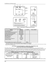
... INCLUDED IN THE CONTROL PANEL'S HARDWARE KIT. Output). ‡Values are limited as PIRs, refer to operate the panel and its attached peripheral devices for keypads means armed with a backup battery which require that the panel's auxiliary power and bell output currents are for standby/alarm; Obtain an Ademco Battery Harness Kit SA5140-1. (Both batteries will fit inside...
... INCLUDED IN THE CONTROL PANEL'S HARDWARE KIT. Output). ‡Values are limited as PIRs, refer to operate the panel and its attached peripheral devices for keypads means armed with a backup battery which require that the panel's auxiliary power and bell output currents are for standby/alarm; Obtain an Ademco Battery Harness Kit SA5140-1. (Both batteries will fit inside...
Operation Guide
Page 9
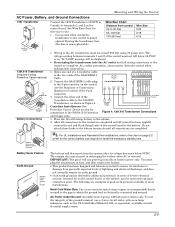
... the ground lead is restored. Do not attach these leads to the battery terminals until all wiring connections to the control are completed. This assists the control panel in Figure 4. Connect the other end of the SA412OXM CABLE 3-conductor cable to the battery. After all connections are complete. UL For UL installations and Residential fire...
... the ground lead is restored. Do not attach these leads to the battery terminals until all wiring connections to the control are completed. This assists the control panel in Figure 4. Connect the other end of the SA412OXM CABLE 3-conductor cable to the battery. After all connections are complete. UL For UL installations and Residential fire...

Operation Guide
Page 10
...(going beyond 2 amps will not function if AC power is required for each partition from the control's auxiliary power output. conn-001-V0 Supplementary Power (optional) UL Use a UL Listed, battery-backed supply for Bell Supervision. Using a Supplementary Power Supply 2-4 ALARM OUTPUT 10.5 - 13.5...negative (-) terminal on the power supply unit to terminal 4 (AUX -) on the PC board. 2. CONTROL TERMINAL STRIP AUX. The battery-backed power supply should have a backup battery will overload the power supply, or may cause the electronic circuit protecting the sounder output to trip). &#...
...(going beyond 2 amps will not function if AC power is required for each partition from the control's auxiliary power output. conn-001-V0 Supplementary Power (optional) UL Use a UL Listed, battery-backed supply for Bell Supervision. Using a Supplementary Power Supply 2-4 ALARM OUTPUT 10.5 - 13.5...negative (-) terminal on the power supply unit to terminal 4 (AUX -) on the PC board. 2. CONTROL TERMINAL STRIP AUX. The battery-backed power supply should have a backup battery will overload the power supply, or may cause the electronic circuit protecting the sounder output to trip). &#...
Operation Guide
Page 14
Installation and Setup Guide WHT GRY VIO BLK YEL ORG BRN RELAY CONNECTOR RELAY 2 DIP SWITCH FOR SETTING ADDRESS AND ZONE "A" RESPONSE RELAY 1 NO C NC TAMPER JUMPER POSITION 4229 IN CABINET (NOT TAMPER) 4229 REMOTE (TAMPER PROTECTED) 12 3456 78 4229 EITHER OR BOTH CAN BE USED TERMINALS ON CONTROL PANEL 4-PIN CONSOLE PLUG TB2 4 TB1 9 10 11 12 3 4 3 22 11 GRN DATA OUT (>) TO CONTROL BLK (-) GROUND RED (+) 12VDC YEL DATA IN (
Installation and Setup Guide WHT GRY VIO BLK YEL ORG BRN RELAY CONNECTOR RELAY 2 DIP SWITCH FOR SETTING ADDRESS AND ZONE "A" RESPONSE RELAY 1 NO C NC TAMPER JUMPER POSITION 4229 IN CABINET (NOT TAMPER) 4229 REMOTE (TAMPER PROTECTED) 12 3456 78 4229 EITHER OR BOTH CAN BE USED TERMINALS ON CONTROL PANEL 4-PIN CONSOLE PLUG TB2 4 TB1 9 10 11 12 3 4 3 22 11 GRN DATA OUT (>) TO CONTROL BLK (-) GROUND RED (+) 12VDC YEL DATA IN (
Operation Guide
Page 15
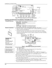
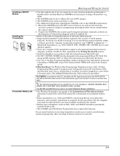
... of this module only if you are not intended for all other zone types. Connect the 5800TM to the control panel's keypad connection terminals as 5801, 5802, and 5802CP) should be ...control). • Button-type transmitters (such as shown on transmitter battery life. • Some transmitters (e.g., 5802 and 5802CP) contain long-life but non-replaceable batteries, and no battery installation is required. UL The following transmitters are ready to enroll during system programming. After enrolling, batteries need not be assigned to a user before it becomes active. VISTA-15P: zones...
... of this module only if you are not intended for all other zone types. Connect the 5800TM to the control panel's keypad connection terminals as 5801, 5802, and 5802CP) should be ...control). • Button-type transmitters (such as shown on transmitter battery life. • Some transmitters (e.g., 5802 and 5802CP) contain long-life but non-replaceable batteries, and no battery installation is required. UL The following transmitters are ready to enroll during system programming. After enrolling, batteries need not be assigned to a user before it becomes active. VISTA-15P: zones...
Operation Guide
Page 21
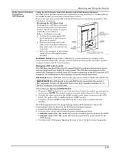
...terminal blocks for 2-way voice operation, install the module according to its instructions. DIP Switch: Set the AVS DIP switch to the control panel. Connecting an Optional GSMV Module a. If using a GSMV module for making connections to remote stations, telephone lines, and to the ...other GSMV wiring following summarizes the programming steps for details of the control's cabinet. b. Secure the assembly to the diagram at right. c. Refer to the cabinet using a 7AH battery, mount the battery vertically on its mounting bracket, which is supplied with the AVS ...
...terminal blocks for 2-way voice operation, install the module according to its instructions. DIP Switch: Set the AVS DIP switch to the control panel. Connecting an Optional GSMV Module a. If using a GSMV module for making connections to remote stations, telephone lines, and to the ...other GSMV wiring following summarizes the programming steps for details of the control's cabinet. b. Secure the assembly to the diagram at right. c. Refer to the cabinet using a 7AH battery, mount the battery vertically on its mounting bracket, which is supplied with the AVS ...
Operation Guide
Page 22
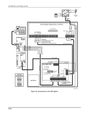
...8 SHOWN) NOT USED AUDIO CONNECTOR HANDSET INCOMING PHONE LINE RING TIP TIP RING AAV PANEL ECP RED BLK GRN YEL RED BLK GRN YEL RED BLK GRN YEL GRY BRN... TO ALL OTHER ECP DEVICES Figure 18. SUPPLIED HARNESS AUDIO CABLE BATTERY (200 FT. Installation and Setup Guide PREMISES PHONES TIP RING 12 87 3 4 5 6...TB 1 1 2 3 4 5 6 7 8 9 10 11 Honeywell GSMV (OPTIONAL) BASE UNIT DEVICE ADDRESS VISTA-15P = 8 ON 12345 VISTA-20P = 11 ON 12345 GRY BRN (EARTH GND VISTA SERIES RESIDENTIAL CONTROL GRN RED ECP TERMINALS DATA DATA GND AUX IN OUT TRIGGER HEADER 1 ...
...8 SHOWN) NOT USED AUDIO CONNECTOR HANDSET INCOMING PHONE LINE RING TIP TIP RING AAV PANEL ECP RED BLK GRN YEL RED BLK GRN YEL RED BLK GRN YEL GRY BRN... TO ALL OTHER ECP DEVICES Figure 18. SUPPLIED HARNESS AUDIO CABLE BATTERY (200 FT. Installation and Setup Guide PREMISES PHONES TIP RING 12 87 3 4 5 6...TB 1 1 2 3 4 5 6 7 8 9 10 11 Honeywell GSMV (OPTIONAL) BASE UNIT DEVICE ADDRESS VISTA-15P = 8 ON 12345 VISTA-20P = 11 ON 12345 GRY BRN (EARTH GND VISTA SERIES RESIDENTIAL CONTROL GRN RED ECP TERMINALS DATA DATA GND AUX IN OUT TRIGGER HEADER 1 ...


