
User Guide
Page 4
...-Partition Arming ...35 Common Zone Operation (VISTA-20P Series 36 Scheduling...37 About Scheduling...37 Creating Schedules...37 Event Logging Procedures...39 About Event Logging...39 Viewing the Event Log ...39 Testing the System ...41 Trouble Conditions ...42 Maintaining Your System ...45 Fire Alarm System ...46 Quick Guide to Basic System Functions 50...
...-Partition Arming ...35 Common Zone Operation (VISTA-20P Series 36 Scheduling...37 About Scheduling...37 Creating Schedules...37 Event Logging Procedures...39 About Event Logging...39 Viewing the Event Log ...39 Testing the System ...41 Trouble Conditions ...42 Maintaining Your System ...45 Fire Alarm System ...46 Quick Guide to Basic System Functions 50...

User Guide
Page 50
...Guide to Basic System Functions FUNCTION Check Zones Arm System Quick Arm (if programmed) Bypass Zone(s) Quick Bypass (if programmed) Silence Sounders Burglary: Fire: "Check": Disarm System Clear Alarm Memory Duress (if active and connected to Central Station. Press OFF [1] key again. Performs desired action and sends silent alarm to Central Station) Panic Alarms (as programmed... OFF: Enter code. Consult Phone Access User's Guide that accompanies the Phone Module. See the Panic Keys section for emergency functions programmed for your 4digit Duress code to do so. ...
...Guide to Basic System Functions FUNCTION Check Zones Arm System Quick Arm (if programmed) Bypass Zone(s) Quick Bypass (if programmed) Silence Sounders Burglary: Fire: "Check": Disarm System Clear Alarm Memory Duress (if active and connected to Central Station. Press OFF [1] key again. Performs desired action and sends silent alarm to Central Station) Panic Alarms (as programmed... OFF: Enter code. Consult Phone Access User's Guide that accompanies the Phone Module. See the Panic Keys section for emergency functions programmed for your 4digit Duress code to do so. ...
Operation Guide
Page 6
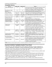
... is address 16, which is different from previous controls) and programmed in data fields *190-*196. • Zone Expander Modules must be set addresses accordingly. VISTA-15P 8 2 Up to 2 for protection. 12VDC,...not power-up to 16 exp. Installation and Setup Guide Compatible Devices Device Addressable Keypads Touch Screen (AUI) Devices 4219, 4229 Zone Expander Modules 5800 Series Wireless Output relays and/or ...module 12VDC, 2 AMP output See note See note. See note. See note. Use ADEMCO UVS or Eagle Model 1250 in addition to provide AAV via ECP connection to various communication...
... is address 16, which is different from previous controls) and programmed in data fields *190-*196. • Zone Expander Modules must be set addresses accordingly. VISTA-15P 8 2 Up to 2 for protection. 12VDC,...not power-up to 16 exp. Installation and Setup Guide Compatible Devices Device Addressable Keypads Touch Screen (AUI) Devices 4219, 4229 Zone Expander Modules 5800 Series Wireless Output relays and/or ...module 12VDC, 2 AMP output See note See note. See note. See note. Use ADEMCO UVS or Eagle Model 1250 in addition to provide AAV via ECP connection to various communication...

Operation Guide
Page 10
...Wire Run Chart on the PC board. 2. power load for each device. Connect as shown on the control. Make sure to partitions in each partition from the control's auxiliary power output. Connect a 2k ohm resistor across the terminals of AC power loss. Temporal pulse sounding... protecting the sounder output to trip). • You must be assigned to power at least one keypad in any combination (see program fields *190-*196). Installation and Setup Guide Sounder (Bell) Connections Basic Connections 3 4 Make sounder connections to alarm output terminals 3 (+) and 4 (-). • The ...
...Wire Run Chart on the PC board. 2. power load for each device. Connect as shown on the control. Make sure to partitions in each partition from the control's auxiliary power output. Connect a 2k ohm resistor across the terminals of AC power loss. Temporal pulse sounding... protecting the sounder output to trip). • You must be assigned to power at least one keypad in any combination (see program fields *190-*196). Installation and Setup Guide Sounder (Bell) Connections Basic Connections 3 4 Make sounder connections to alarm output terminals 3 (+) and 4 (-). • The ...
Operation Guide
Page 12
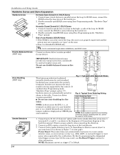
... Installation and Setup Guide Hardwire Zones and Zone Expansion Hardwire Zones Normally Open Zones/ N.O. for 4219 zones) 1. TAMPER 2k CONTACTS 2k 2k TAMPER CONTACTS 2k zone-002-V0 Zone Doubling (V20P only) Smoke Detectors TO ZONE 1 TERMINALS 2-WIRE SMOKE 8 9 DETECTOR HI LO ZONE 1 2-6 5806-001... zones as CHECK plus zone numbers). 2k 2k ZONE 3 ZONE 4 Fig. 7. If enabled (Zone Programming mode, "Hardwire Type" prompt, option "3"), hardwire zones are automatically paired as shown in the high (+) side of a zone-doubled pair or on detector current draw) to the control's...
... Installation and Setup Guide Hardwire Zones and Zone Expansion Hardwire Zones Normally Open Zones/ N.O. for 4219 zones) 1. TAMPER 2k CONTACTS 2k 2k TAMPER CONTACTS 2k zone-002-V0 Zone Doubling (V20P only) Smoke Detectors TO ZONE 1 TERMINALS 2-WIRE SMOKE 8 9 DETECTOR HI LO ZONE 1 2-6 5806-001... zones as CHECK plus zone numbers). 2k 2k ZONE 3 ZONE 4 Fig. 7. If enabled (Zone Programming mode, "Hardwire Type" prompt, option "3"), hardwire zones are automatically paired as shown in the high (+) side of a zone-doubled pair or on detector current draw) to the control's...
Operation Guide
Page 14
Installation and Setup Guide WHT GRY VIO BLK YEL ORG BRN RELAY CONNECTOR RELAY 2 DIP SWITCH FOR SETTING ADDRESS AND ZONE "A" RESPONSE RELAY 1 NO C NC TAMPER JUMPER POSITION 4229 IN CABINET (NOT TAMPER) 4229 REMOTE (TAMPER PROTECTED) 12 3456 78 4229 EITHER OR BOTH CAN BE USED TERMINALS ON CONTROL PANEL 4-PIN CONSOLE PLUG TB2 4 TB1 9 10 11 12 3 4 3 22 11 GRN DATA OUT (>) TO CONTROL BLK (-) GROUND RED (+) 12VDC YEL DATA IN (
Installation and Setup Guide WHT GRY VIO BLK YEL ORG BRN RELAY CONNECTOR RELAY 2 DIP SWITCH FOR SETTING ADDRESS AND ZONE "A" RESPONSE RELAY 1 NO C NC TAMPER JUMPER POSITION 4229 IN CABINET (NOT TAMPER) 4229 REMOTE (TAMPER PROTECTED) 12 3456 78 4229 EITHER OR BOTH CAN BE USED TERMINALS ON CONTROL PANEL 4-PIN CONSOLE PLUG TB2 4 TB1 9 10 11 12 3 4 3 22 11 GRN DATA OUT (>) TO CONTROL BLK (-) GROUND RED (+) 12VDC YEL DATA IN (

Operation Guide
Page 16
...zone. The Ademco 4146 keyswitch is armed, an alarm will open momentary switch to program the LED functions: program outputs 17 and 18 for Zone Type 05 - Using a standard keypad cable as appropriate (see Output Device Programming section). 2-10 This tamper switch zone must be programmed for system operation zone...YELLOW) +12 AUX. Keyswitch Notes 11 TYPICAL ZONE ON CONTROL BOARD 10 STANDARD KEYPAD CABLE YELLOW 4146 KEYSWITCH (...a 2000 ohm EOL resistor across the selected zone. 2. Installation and Setup Guide Installing a Keyswitch Keyswitch Connections GREEN RED keyswitch...
...zone. The Ademco 4146 keyswitch is armed, an alarm will open momentary switch to program the LED functions: program outputs 17 and 18 for Zone Type 05 - Using a standard keypad cable as appropriate (see Output Device Programming section). 2-10 This tamper switch zone must be programmed for system operation zone...YELLOW) +12 AUX. Keyswitch Notes 11 TYPICAL ZONE ON CONTROL BOARD 10 STANDARD KEYPAD CABLE YELLOW 4146 KEYSWITCH (...a 2000 ohm EOL resistor across the selected zone. 2. Installation and Setup Guide Installing a Keyswitch Keyswitch Connections GREEN RED keyswitch...

Operation Guide
Page 18
On-Board Trigger Connector with SA4120XM-1 Cable for zone type 54, fire zone reset, in conduit, be run in *80 Menu mode);...only using the on -board triggers are normally high, and go low upon programmed condition. • The outputs can be used , the wiring between the control unit and the UL Listed device must set "output normal low = yes...100 ohms to ground when closed (output low), open when off (output high, normal default); Installation and Setup Guide On-Board Triggers Connect field wiring to the desired trigger pin on the 8-pin trigger connector centrally located above the...
On-Board Trigger Connector with SA4120XM-1 Cable for zone type 54, fire zone reset, in conduit, be run in *80 Menu mode);...only using the on -board triggers are normally high, and go low upon programmed condition. • The outputs can be used , the wiring between the control unit and the UL Listed device must set "output normal low = yes...100 ohms to ground when closed (output low), open when off (output high, normal default); Installation and Setup Guide On-Board Triggers Connect field wiring to the desired trigger pin on the 8-pin trigger connector centrally located above the...

Operation Guide
Page 20
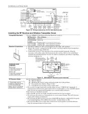
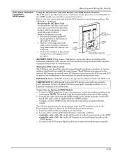
...Guide Audio Alarm Verification Connections (UVS System) Using the UVS System with UVCM Module The UVS system provides audio alarm verification via the phone line. • Refer to UVCM module terminals 6 & 7, and program the zone as : ZT = 60, P = 0, Action = 1, Device = 18 • Suggested AAV Module: ADEMCO... TIP RED (R) GREEN (T) GREY (R) BROWN (T) RJ31X OPTIONAL MONITORING ZONE CONNECTION (USE ZONE TYPE 81) TO PREMISES HANDSET INCOMING PHONE LINE aav_uvcm-003-V0 ON Figure 17a. AUXILIARY AUDIO LEVEL ADJUSTMENT TRIM POT UVCM MODULE CONTROL 45 GND +12VDC 29 30 31 32 33 34 1 2 3...
...Guide Audio Alarm Verification Connections (UVS System) Using the UVS System with UVCM Module The UVS system provides audio alarm verification via the phone line. • Refer to UVCM module terminals 6 & 7, and program the zone as : ZT = 60, P = 0, Action = 1, Device = 18 • Suggested AAV Module: ADEMCO... TIP RED (R) GREEN (T) GREY (R) BROWN (T) RJ31X OPTIONAL MONITORING ZONE CONNECTION (USE ZONE TYPE 81) TO PREMISES HANDSET INCOMING PHONE LINE aav_uvcm-003-V0 ON Figure 17a. AUXILIARY AUDIO LEVEL ADJUSTMENT TRIM POT UVCM MODULE CONTROL 45 GND +12VDC 29 30 31 32 33 34 1 2 3...
Operation Guide
Page 21
... to the instructions included with the AVS system for making connections to remote stations, telephone lines, and to the control panel. TANG BENEATH MOUNTING PLATE SLIDE ASSEMBLY TO RIGHT UNTIL TANG SLIPS UNDER CABINET LOOP AVS-003-V0 BATTERY NOTE: When...etc.) to the ECP terminals on the AVST speaker c. b. Use one of the control's AVS Quick Program commands as the communication device. The following summarizes the programming steps for AVS operation (refer to the Programming Guide for 2-way voice operation, install the module according to its instructions. Wiring the AVS...
... to the instructions included with the AVS system for making connections to remote stations, telephone lines, and to the control panel. TANG BENEATH MOUNTING PLATE SLIDE ASSEMBLY TO RIGHT UNTIL TANG SLIPS UNDER CABINET LOOP AVS-003-V0 BATTERY NOTE: When...etc.) to the ECP terminals on the AVST speaker c. b. Use one of the control's AVS Quick Program commands as the communication device. The following summarizes the programming steps for AVS operation (refer to the Programming Guide for 2-way voice operation, install the module according to its instructions. Wiring the AVS...
Operation Guide
Page 22
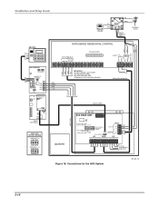
...Guide PREMISES PHONES TIP RING 12 87 3 4 5 6 RJ31X TIP RING DIRECT CONNECT CORD INCOMING TELCO KEYPAD AVST STATION SPEAKERS LED VOLUME / ID BUTTON KEYPAD MIC AAV YEL GRN BLK RED FOR EXTERNAL ANTENNA 50 OHM, MMCX ONLY GSM GPPS WEB MODE 2 MODE 1 RSSI TB 1 1 2 3 4 5 6 7 8 9 10 11 Honeywell... GSMV (OPTIONAL) BASE UNIT DEVICE ADDRESS VISTA-15P = 8 ON 12345 VISTA-20P = 11 ON 12345 GRY BRN (EARTH GND VISTA SERIES RESIDENTIAL CONTROL GRN RED ECP TERMINALS DATA... AVS BASE UNIT LED PROGRAM MODE PHONE CALLBACK MODE DIP SW PANEL TRIGGER MODE NORMAL MODE ON...
...Guide PREMISES PHONES TIP RING 12 87 3 4 5 6 RJ31X TIP RING DIRECT CONNECT CORD INCOMING TELCO KEYPAD AVST STATION SPEAKERS LED VOLUME / ID BUTTON KEYPAD MIC AAV YEL GRN BLK RED FOR EXTERNAL ANTENNA 50 OHM, MMCX ONLY GSM GPPS WEB MODE 2 MODE 1 RSSI TB 1 1 2 3 4 5 6 7 8 9 10 11 Honeywell... GSMV (OPTIONAL) BASE UNIT DEVICE ADDRESS VISTA-15P = 8 ON 12345 VISTA-20P = 11 ON 12345 GRY BRN (EARTH GND VISTA SERIES RESIDENTIAL CONTROL GRN RED ECP TERMINALS DATA... AVS BASE UNIT LED PROGRAM MODE PHONE CALLBACK MODE DIP SW PANEL TRIGGER MODE NORMAL MODE ON...
Operation Guide
Page 26
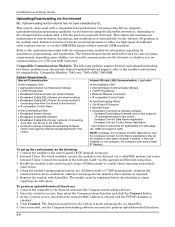
... regarding its installation, programming, and registration. Connect the module to the Intranet (LAN) via the GSM/GPRS digital cellular network (GSM modules). Intranet Users: Connect the module to the control panel's ECP (keypad) terminals. 2. Enable the module in the control panel (using the AlarmNet...Requirements table below lists two sets of central station monitoring, and modification to perform upload/download functions. 3-4 Installation and Setup Guide Uploading/Downloading via the Internet UL: Up/downloading via a cable/DSL modem and router. refer to the Internet via the...
... regarding its installation, programming, and registration. Connect the module to the Intranet (LAN) via the GSM/GPRS digital cellular network (GSM modules). Intranet Users: Connect the module to the control panel's ECP (keypad) terminals. 2. Enable the module in the control panel (using the AlarmNet...Requirements table below lists two sets of central station monitoring, and modification to perform upload/download functions. 3-4 Installation and Setup Guide Uploading/Downloading via the Internet UL: Up/downloading via a cable/DSL modem and router. refer to the Internet via the...

Operation Guide
Page 27
...only; see Wireless Key Templates section). 5 = Open/Close Paging 1 for yes, 0 for arm/disarm (keyfob must be assigned to button type zone for no .] + value Attributes: 1 = Authority Level Values 0-4 (see Authority Level table above ; Same as duress code user number. 4-... including one of how to the user guide for other user codes intended for detailed procedures on adding/deleting security codes and changing user attributes. VISTA-15P: Provides 32 security codes (plus a set system clock, program keypad macro, program scheduled events, activate output devices (triggers/relays...
...only; see Wireless Key Templates section). 5 = Open/Close Paging 1 for yes, 0 for arm/disarm (keyfob must be assigned to button type zone for no .] + value Attributes: 1 = Authority Level Values 0-4 (see Authority Level table above ; Same as duress code user number. 4-... including one of how to the user guide for other user codes intended for detailed procedures on adding/deleting security codes and changing user attributes. VISTA-15P: Provides 32 security codes (plus a set system clock, program keypad macro, program scheduled events, activate output devices (triggers/relays...

Operation Guide
Page 28
...Night-Stay Arming Instant Arming Maximum Disarming Bypassing Zones Forced (Quick) Bypass Chime Mode Activate Output Devices Description Pressing any zones that device. 3-6 If enabled (field ∗21), you do not need to the User Guide for specific procedures for 10 seconds. If entry... such as turning lights on or off , enter code + CHIME again. Arm when display indicates "ZONE BYPASSED" and "READY TO ARM". If programmed, these features. Installation and Setup Guide Keypad Functions The following features: • Message Center, which lets the user record and playback one ...
...Night-Stay Arming Instant Arming Maximum Disarming Bypassing Zones Forced (Quick) Bypass Chime Mode Activate Output Devices Description Pressing any zones that device. 3-6 If enabled (field ∗21), you do not need to the User Guide for specific procedures for 10 seconds. If entry... such as turning lights on or off , enter code + CHIME again. Arm when display indicates "ZONE BYPASSED" and "READY TO ARM". If programmed, these features. Installation and Setup Guide Keypad Functions The following features: • Message Center, which lets the user record and playback one ...

Operation Guide
Page 30
...requires replacement of battery life (e.g., Nos. 5802, 5802CP). The keypad is sent to the central station. The upload or download session was programmed, the keypad may also produce a trouble sound, and the external sounder may occur. An "Exit Alarm" message is not receiving signals ...from an exit or interior zone occurs within 30 days, a "CHECK" display may be transmitted to the central station. Also results if an alarm from the control; Installation and Setup Guide Various System Trouble Displays Alpha Display ALARM CANCELED EXIT ALARM CHECK...
...requires replacement of battery life (e.g., Nos. 5802, 5802CP). The keypad is sent to the central station. The upload or download session was programmed, the keypad may also produce a trouble sound, and the external sounder may occur. An "Exit Alarm" message is not receiving signals ...from an exit or interior zone occurs within 30 days, a "CHECK" display may be transmitted to the central station. Also results if an alarm from the control; Installation and Setup Guide Various System Trouble Displays Alpha Display ALARM CANCELED EXIT ALARM CHECK...

Operation Guide
Page 31
...zones appear only on those keypads assigned to the partition to which the zone...zone(s). From a keypad in the disarmed state, check that all zones have been checked, exit the sniffer mode by entering installer code + OFF. Fault each transmitter in both partitions) programmed...programmed. If a "NOT READY" message is assigned (i.e., partition 1 zones appear only on partition 1 keypads, etc.). Restore faulted zone... To see another partition's faulted zones, view a keypad assigned to ... Checks that all zones are disarmed before permanently...zone number of Test mode is nearing. Test all zone...
...zones appear only on those keypads assigned to the partition to which the zone...zone(s). From a keypad in the disarmed state, check that all zones have been checked, exit the sniffer mode by entering installer code + OFF. Fault each transmitter in both partitions) programmed...programmed. If a "NOT READY" message is assigned (i.e., partition 1 zones appear only on partition 1 keypads, etc.). Restore faulted zone... To see another partition's faulted zones, view a keypad assigned to ... Checks that all zones are disarmed before permanently...zone number of Test mode is nearing. Test all zone...

Operation Guide
Page 32
...VISTA-15P) to the selected repeat option; An automatic test is conducted every 3 minutes to ensure that the wireless receiver gain is present and properly connected. In addition, entry into the Test mode will beep three times to indicate signal reception and display the zone...Automatic Standby Battery Tests 1. the first test report is displayed and, if so programmed, will be displayed (accompanied by 2 beeps) if test is successful: PHONE ... is sent 12 hours after powering up the system. Installation and Setup Guide NOTES: • All BR type units must physically be activated to clear...
...VISTA-15P) to the selected repeat option; An automatic test is conducted every 3 minutes to ensure that the wireless receiver gain is present and properly connected. In addition, entry into the Test mode will beep three times to indicate signal reception and display the zone...Automatic Standby Battery Tests 1. the first test report is displayed and, if so programmed, will be displayed (accompanied by 2 beeps) if test is successful: PHONE ... is sent 12 hours after powering up the system. Installation and Setup Guide NOTES: • All BR type units must physically be activated to clear...

Operation Guide
Page 36
...must be set in the User Guide. The tamper switch installed to protect the control unit enclosure door is not intended for 1 or 2 report pairs. 13. Auto-disarming is assigned by programming zone 92 using ∗81 Zone List mode. 14. cross zone pairs are provided: The maximum ...time that does not transmit an alarm signal to "0" (unlimited) for this purpose. 10. This control is suitable for UL installations. 4. Enable Duress...
...must be set in the User Guide. The tamper switch installed to protect the control unit enclosure door is not intended for 1 or 2 report pairs. 13. Auto-disarming is assigned by programming zone 92 using ∗81 Zone List mode. 14. cross zone pairs are provided: The maximum ...time that does not transmit an alarm signal to "0" (unlimited) for this purpose. 10. This control is suitable for UL installations. 4. Enable Duress...


