
Owner's Manual
Page 3
Table Of Contents PAGE Features Of Your Thermostat ...4 Setting The Temperature ...7 Setting Subbase Switches ...8 Inserting Timer Backup Batteries ...9 Setting The Timer ...10 Programming ...11 Troubleshooting ...14 Servicing The Thermostat ...21 Warranty ...23 3 69-0563-2
Table Of Contents PAGE Features Of Your Thermostat ...4 Setting The Temperature ...7 Setting Subbase Switches ...8 Inserting Timer Backup Batteries ...9 Setting The Timer ...10 Programming ...11 Troubleshooting ...14 Servicing The Thermostat ...21 Warranty ...23 3 69-0563-2
Owner's Manual
Page 14
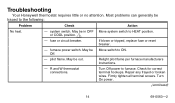
.... Off. - R and W thermostat connections. Turn On power. (continued) 14 69-0563-2 pilot flame. Turn Off power to HEAT position. Check for correct terminal hookups. Troubleshooting Your Honeywell thermostat requires little or no attention. May be in OFF or COOL position. 1 - Relight pilot flame per furnace manufacturers instructions. - May be out. Repair any...
.... Off. - R and W thermostat connections. Turn On power. (continued) 14 69-0563-2 pilot flame. Turn Off power to HEAT position. Check for correct terminal hookups. Troubleshooting Your Honeywell thermostat requires little or no attention. May be in OFF or COOL position. 1 - Relight pilot flame per furnace manufacturers instructions. - May be out. Repair any...
Owner's Manual
Page 15
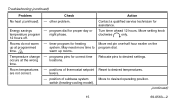
... - levers. - programs pins for heating system. Relocate pins to desired temperatures. Move to warm up at programmed time. 2 Temperature change occurs at the wrong time. - Troubleshooting (continued) Problem Check Action No heat (continued). -
... - levers. - programs pins for heating system. Relocate pins to desired temperatures. Move to warm up at programmed time. 2 Temperature change occurs at the wrong time. - Troubleshooting (continued) Problem Check Action No heat (continued). -
Owner's Manual
Page 16
... setting levers 5°F (3°C) above room temperature. Cooling system should start . With system switch at HEAT, move temperature setting levers 5°F (3°C) below room temperature. Troubleshooting (continued) Problem Room temperatures are not correct (continued).
... setting levers 5°F (3°C) above room temperature. Cooling system should start . With system switch at HEAT, move temperature setting levers 5°F (3°C) below room temperature. Troubleshooting (continued) Problem Room temperatures are not correct (continued).
Owner's Manual
Page 17
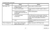
system switch. condenser switch position. other Timer is Off. Move to COOL position. Firmly tighten all terminal screws. Make sure power is losing time. - Troubleshooting (continued) Problem Check No cooling. 1 - Power. May be in OFF or HEAT position. - Action Move switch to ON position. If fuse is On. Check for ...
system switch. condenser switch position. other Timer is Off. Move to COOL position. Firmly tighten all terminal screws. Make sure power is losing time. - Troubleshooting (continued) Problem Check No cooling. 1 - Power. May be in OFF or HEAT position. - Action Move switch to ON position. If fuse is On. Check for ...
Owner's Manual
Page 18
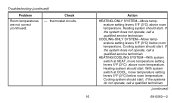
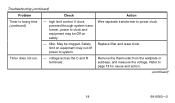
filter. Safety limit on safety. Replace filter and reset clock. Refer to power clock. Timer does not run. - May be Off on equipment may cut off power to clock and equipment may be clogged. voltage across the C and R terminals. high limit control. Troubleshooting (continued) Problem Timer is losing time (continued). Check Action - Wire separate transformer to page 19 for cause and action. (continued) 18 69-0563-2 Remove the thermostat from the wallplate or subbase, and measure the voltage. If clock powered through system transformer, power to system. -
filter. Safety limit on safety. Replace filter and reset clock. Refer to power clock. Timer does not run. - May be Off on equipment may cut off power to clock and equipment may be clogged. voltage across the C and R terminals. high limit control. Troubleshooting (continued) Problem Timer is losing time (continued). Check Action - Wire separate transformer to page 19 for cause and action. (continued) 18 69-0563-2 Remove the thermostat from the wallplate or subbase, and measure the voltage. If clock powered through system transformer, power to system. -
Owner's Manual
Page 19
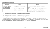
...- Use a spirit level. Contact qualified service technician for drafts or radiant heat. reading disagree. - Action Reinstall thermostat subbase. Troubleshooting (continued) Problem Check Thermostat setting and thermometer. level position of location. 1 Not applicable on model used in cooling-only system.... to 5:30 p.m., Central time. 19 69-0563-2 If this Troubleshooting section has not solved the problem, call a qualified service technician or Honeywell Customer Assistance Center, Honeywell Inc., P.O., Box 524, Minneapolis, MN 55440-0524 or call 1-800-468-1502,...
...- Use a spirit level. Contact qualified service technician for drafts or radiant heat. reading disagree. - Action Reinstall thermostat subbase. Troubleshooting (continued) Problem Check Thermostat setting and thermometer. level position of location. 1 Not applicable on model used in cooling-only system.... to 5:30 p.m., Central time. 19 69-0563-2 If this Troubleshooting section has not solved the problem, call a qualified service technician or Honeywell Customer Assistance Center, Honeywell Inc., P.O., Box 524, Minneapolis, MN 55440-0524 or call 1-800-468-1502,...
Installation Instructions
Page 5
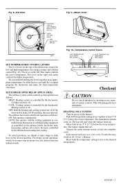
... 80 M8604 M5161 Fig. 10-Temperature control levers. This will start when the furnace heats up. Fig. 9-Attach cover. The lever on power to the Troubleshooting Guide in detent over the desired function indicator mark. 50 60 70 80 M859 Checkout CAUTION Do not check operation by shorting across terminals of...
... 80 M8604 M5161 Fig. 10-Temperature control levers. This will start when the furnace heats up. Fig. 9-Attach cover. The lever on power to the Troubleshooting Guide in detent over the desired function indicator mark. 50 60 70 80 M859 Checkout CAUTION Do not check operation by shorting across terminals of...
Installation Instructions
Page 6
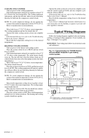
...fails any time delay that may be built into the compressor control circuit. Fig. 11-Typical hookup for any test, refer to the Troubleshooting Guide in the Owner's Manual. NOTE: To avoid compressor damage, do not operate the system when outdoor temperature is below 50°...levers to the desired temperatures. The burner should shut off . The cooling equipment will operate, and the fan will start . Allow for T8195B Thermostat and Q682C Wallplate in gas heating control system. Reset both the temperature setting levers to the desired temperatures. TIMER THERMOSTAT H FALL ...
...fails any time delay that may be built into the compressor control circuit. Fig. 11-Typical hookup for any test, refer to the Troubleshooting Guide in the Owner's Manual. NOTE: To avoid compressor damage, do not operate the system when outdoor temperature is below 50°...levers to the desired temperatures. The burner should shut off . The cooling equipment will operate, and the fan will start . Allow for T8195B Thermostat and Q682C Wallplate in gas heating control system. Reset both the temperature setting levers to the desired temperatures. TIMER THERMOSTAT H FALL ...


