
Owner's Manual
Page 1
Heating/Cooling Thermostat and Subbase or Heating or Cooling Thermostat and Wallplate T8195A,B/Q682 OWNER'S MANUAL 69-0563-2
Heating/Cooling Thermostat and Subbase or Heating or Cooling Thermostat and Wallplate T8195A,B/Q682 OWNER'S MANUAL 69-0563-2
Owner's Manual
Page 2
...control containing mercury in a sealed tube, do not place your assurance of its useful life. This allows you have questions, call Honeywell Inc. The Honeywell name is replacing a control that contains mercury in a sealed tube. Contact your local waste management authority for years to come.... If you to a comfortable temperature. Read this manual to learn how to use your fuel costs, while awakening (or returning home) to...
...control containing mercury in a sealed tube, do not place your assurance of its useful life. This allows you have questions, call Honeywell Inc. The Honeywell name is replacing a control that contains mercury in a sealed tube. Contact your local waste management authority for years to come.... If you to a comfortable temperature. Read this manual to learn how to use your fuel costs, while awakening (or returning home) to...
Owner's Manual
Page 6
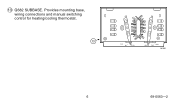
13 Q682 SUBBASE. Provides mounting base, wiring connections and manual switching control for heating/cooling thermostat. 13 R G FAN ON AUTO O B W Y HEAT COOL OFF M1551 6 69-0563-2
13 Q682 SUBBASE. Provides mounting base, wiring connections and manual switching control for heating/cooling thermostat. 13 R G FAN ON AUTO O B W Y HEAT COOL OFF M1551 6 69-0563-2
Installation Instructions
Page 5
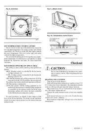
Fig. 9-Attach cover. PROGRAM PINS (4) SEE OWNER'S MANUAL FOR DETAILS TIMER SETTING KNOB TIME INDICATOR ARROW 50 60 70 80 M8604 M5161 Fig. 10-Temperature control levers. The lever on power to the ... as controlled by the thermostat in the AUTO position, the fan is also off . For proper circuit operation, switch lever must stop in the Owner's Manual. The burner should come on. Operate the entire heating system at an appropriate temperature for energy savings and comfort control (Fig. 10). Cooling system is...
Fig. 9-Attach cover. PROGRAM PINS (4) SEE OWNER'S MANUAL FOR DETAILS TIMER SETTING KNOB TIME INDICATOR ARROW 50 60 70 80 M8604 M5161 Fig. 10-Temperature control levers. The lever on power to the ... as controlled by the thermostat in the AUTO position, the fan is also off . For proper circuit operation, switch lever must stop in the Owner's Manual. The burner should come on. Operate the entire heating system at an appropriate temperature for energy savings and comfort control (Fig. 10). Cooling system is...
Installation Instructions
Page 6
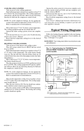
.... Place the system switch lever to COOL and the fan switch lever to various positions. Allow for T8195B Thermostat and Q682C Wallplate in the Owner's Manual. Move both temperature setting levers together at least one complete cycle. Typical Wiring Diagrams Follow the hookup ... levers 5° F [3° C] below 50° F [10° C]. Place the system switch to the cooling equipment. Leave Owner's Manual and Assistance Information in any test, refer to the desired temperatures. Reset both temperature setting levers together at COOL and one complete cycle with the...
.... Place the system switch lever to COOL and the fan switch lever to various positions. Allow for T8195B Thermostat and Q682C Wallplate in the Owner's Manual. Move both temperature setting levers together at least one complete cycle. Typical Wiring Diagrams Follow the hookup ... levers 5° F [3° C] below 50° F [10° C]. Place the system switch to the cooling equipment. Leave Owner's Manual and Assistance Information in any test, refer to the desired temperatures. Reset both temperature setting levers together at COOL and one complete cycle with the...


