
Owner's Manual
Page 2
...in new heating and cooling systems. During heating and cooling, this control is your assurance of accurate control and reliable operation for instructions regarding recycling and the proper disposal of energy savings with your new thermostat. If this thermostat will automatically lower and raise the ... local waste management authority for years to the world of this manual to learn how to a comfortable temperature. Welcome to come. The Honeywell name is replacing a control that contains mercury in a sealed tube, do not place your old control in the trash at 1-800-468...
...in new heating and cooling systems. During heating and cooling, this control is your assurance of accurate control and reliable operation for instructions regarding recycling and the proper disposal of energy savings with your new thermostat. If this thermostat will automatically lower and raise the ... local waste management authority for years to the world of this manual to learn how to a comfortable temperature. Welcome to come. The Honeywell name is replacing a control that contains mercury in a sealed tube, do not place your old control in the trash at 1-800-468...
Owner's Manual
Page 14
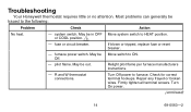
.... - pilot flame. Repair any frayed or broken wires. Firmly tighten all terminal screws. furnace power switch. Relight pilot flame per furnace manufacturers instructions. - Check for correct terminal hookups. Troubleshooting Your Honeywell thermostat requires little or no attention. fuse or circuit breaker. May be in OFF or COOL position. 1 - R and W thermostat connections. May...
.... - pilot flame. Repair any frayed or broken wires. Firmly tighten all terminal screws. furnace power switch. Relight pilot flame per furnace manufacturers instructions. - Check for correct terminal hookups. Troubleshooting Your Honeywell thermostat requires little or no attention. fuse or circuit breaker. May be in OFF or COOL position. 1 - R and W thermostat connections. May...
Owner's Manual
Page 22
Before you call our toll-free Customer assistance Center group number at 1-800-468-1502, Monday-Friday, 7:00 a.m. - 5:30 p.m. Central time. For all questions concerning this thermostat, please read and follow the instructions. If additional assistance is needed, call , please have the following information available: make and model of furnace, thermostat and air conditioner. 22 69-0563-2
Before you call our toll-free Customer assistance Center group number at 1-800-468-1502, Monday-Friday, 7:00 a.m. - 5:30 p.m. Central time. For all questions concerning this thermostat, please read and follow the instructions. If additional assistance is needed, call , please have the following information available: make and model of furnace, thermostat and air conditioner. 22 69-0563-2
Installation Instructions
Page 1
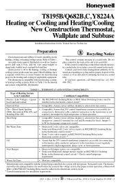
...Honeywell damper motors require an R8239D1015 Isolating Relay in the thermostat control circuit.a, b Oil • Assure that the 24V control transformer common is selected for the Trained Service Technician. T8195B/Q682B,C, Y8224A Heating or Cooling and Heating/Cooling New Construction Thermostat, Wallplate and Subbase Installation Instructions... Spark Ignition • Compatible. For proper system operation, a Honeywell R841 or R8239D1015 Isolating Relay must be added to Table 1 for instructions regarding recycling and the proper disposal of this control is replacing ...
...Honeywell damper motors require an R8239D1015 Isolating Relay in the thermostat control circuit.a, b Oil • Assure that the 24V control transformer common is selected for the Trained Service Technician. T8195B/Q682B,C, Y8224A Heating or Cooling and Heating/Cooling New Construction Thermostat, Wallplate and Subbase Installation Instructions... Spark Ignition • Compatible. For proper system operation, a Honeywell R841 or R8239D1015 Isolating Relay must be added to Table 1 for instructions regarding recycling and the proper disposal of this control is replacing ...
Installation Instructions
Page 2
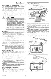
... ducts. - Use spirit level to the new thermostat location. Pull wires through the large wiring hole in corners. - Read these instructions. concealed pipes and chimneys. - Fig. 2-Mounting wallplate or subbase to Fig. 1. Do not short across coil terminals on wall ... PLASTIC ANCHORS HEATING-ONLY WALLPLATE M857 69-0564-3 2 LOCATION Locate thermostat about 5 ft [1.5m] above the floor in these instructions carefully. Failure to subbase threads can burn out the thermostat heat anticipator. Installation WHEN INSTALLING THIS PRODUCT... 1. Set aside cover...
... ducts. - Use spirit level to the new thermostat location. Pull wires through the large wiring hole in corners. - Read these instructions. concealed pipes and chimneys. - Fig. 2-Mounting wallplate or subbase to Fig. 1. Do not short across coil terminals on wall ... PLASTIC ANCHORS HEATING-ONLY WALLPLATE M857 69-0564-3 2 LOCATION Locate thermostat about 5 ft [1.5m] above the floor in these instructions carefully. Failure to subbase threads can burn out the thermostat heat anticipator. Installation WHEN INSTALLING THIS PRODUCT... 1. Set aside cover...
Installation Instructions
Page 3
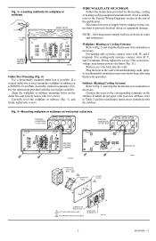
.... Push excess wire back into the wall. If labels do not agree with your new subbase, refer to Table 2 and the installation instructions furnished with nonhardening caulk, putty, or nonflammable insulation to Fig. 5 and strip the thermostat wire insulation as necessary. MOUNTING SCREWS (2) M1554A.... If not available, refer to prevent electrical shock or equipment damage. Fig. 3-Leveling methods for wallplate or subbase. Follow the instructions provided with the cover plate assembly. Carefully level the wallplate or subbase (Fig. 3), and firmly tighten the screws. Disconnect the ...
.... Push excess wire back into the wall. If labels do not agree with your new subbase, refer to Table 2 and the installation instructions furnished with nonhardening caulk, putty, or nonflammable insulation to Fig. 5 and strip the thermostat wire insulation as necessary. MOUNTING SCREWS (2) M1554A.... If not available, refer to prevent electrical shock or equipment damage. Fig. 3-Leveling methods for wallplate or subbase. Follow the instructions provided with the cover plate assembly. Carefully level the wallplate or subbase (Fig. 3), and firmly tighten the screws. Disconnect the ...


