
Owner's Manual
Page 2
The Honeywell name is replacing a control that contains mercury in a sealed tube, do not place your old control in a sealed tube. Read this thermostat will automatically lower ... tube. If you to significantly lower your new Honeywell thermostat. This allows you have questions, call Honeywell Inc. Recycling Notice M3375 This control contains mercury in the trash. If this control is your new thermostat. This thermostat meets California Title 24 requirements-mandatory installation of automatic setback thermostats in new heating and cooling...
The Honeywell name is replacing a control that contains mercury in a sealed tube, do not place your old control in a sealed tube. Read this thermostat will automatically lower ... tube. If you to significantly lower your new Honeywell thermostat. This allows you have questions, call Honeywell Inc. Recycling Notice M3375 This control contains mercury in the trash. If this control is your new thermostat. This thermostat meets California Title 24 requirements-mandatory installation of automatic setback thermostats in new heating and cooling...
Owner's Manual
Page 9
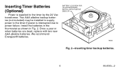
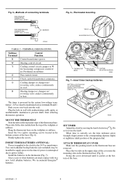
Once a year or when batteries are dead, replace with two new AAA alkaline batteries. We recommend Energizer® batteries. Inserting Timer Batteries (Optional) Power is interrupted due to the timer by the 24 Vac transformer. Install the batteries in the thermostat as shown in Fig. 2. BATTERY LOCATION FOR (2) AAA BATTERIES; Two AAA alkaline backup batteries (not included) may be installed to supply power to the timer if power is supplied to power failure. INSTALL WITH POSITIVE ENDS UP M8585 Fig. 2-Inserting timer backup batteries. 9 69-0563-2
Once a year or when batteries are dead, replace with two new AAA alkaline batteries. We recommend Energizer® batteries. Inserting Timer Batteries (Optional) Power is interrupted due to the timer by the 24 Vac transformer. Install the batteries in the thermostat as shown in Fig. 2. BATTERY LOCATION FOR (2) AAA BATTERIES; Two AAA alkaline backup batteries (not included) may be installed to supply power to the timer if power is supplied to power failure. INSTALL WITH POSITIVE ENDS UP M8585 Fig. 2-Inserting timer backup batteries. 9 69-0563-2
Owner's Manual
Page 20
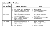
... 69-0563-2 Additional (separate) transformer used to 30 Vac. 1. Replace wiring. 3. Use additional (separate) transformer. 2. Limit switch contacts stuck open. 4. Transformer supplying power is Off. 2. Install transformer with subbase terminals. 2. Restore power. 2. System transformer used to power the timer has inadequate voltage. 15 to power the timer is inadequate. 2. Action 1.
... 69-0563-2 Additional (separate) transformer used to 30 Vac. 1. Replace wiring. 3. Use additional (separate) transformer. 2. Limit switch contacts stuck open. 4. Transformer supplying power is Off. 2. Install transformer with subbase terminals. 2. Restore power. 2. System transformer used to power the timer has inadequate voltage. 15 to power the timer is inadequate. 2. Action 1.
Installation Instructions
Page 1
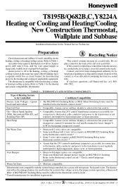
... tube. Contact your old control in . D.F. • Rev. 11-94 • 1 • ©Honeywell Inc. 1994 • Form Number6699--00556644--3 M3375 T8195B/Q682B,C, Y8224A Heating or Cooling and Heating/Cooling New Construction Thermostat, Wallplate and Subbase Installation Instructions for installation requirements. Refer to the transformer is not compatible with 3/16-in the trash. If...
... tube. Contact your old control in . D.F. • Rev. 11-94 • 1 • ©Honeywell Inc. 1994 • Form Number6699--00556644--3 M3375 T8195B/Q682B,C, Y8224A Heating or Cooling and Heating/Cooling New Construction Thermostat, Wallplate and Subbase Installation Instructions for installation requirements. Refer to the transformer is not compatible with 3/16-in the trash. If...
Installation Instructions
Page 2
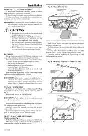
...equipment damage. 2. Remove the thermostat cover by : - holes, and gently tap anchors into holes until needed later. After installation is level. Do not overtighten thermostat captive mounting screws because damage to the new thermostat location. Set aside cover until flush...6 LIFT COVER 9 8 76 10 5 3 2 1 12 4 THERMOSTAT BASE REMOVE PACKING MATERIAL M8605 Drill 3/16-in position on wall (Fig. 2). Installer must be pulled, a 4-wire heating/cooling requires five wires). It is not a calibration problem. MOUNT WALLPLATE OR SUBBASE Wall Mounting (Fig. 2) Hold the...
...equipment damage. 2. Remove the thermostat cover by : - holes, and gently tap anchors into holes until needed later. After installation is level. Do not overtighten thermostat captive mounting screws because damage to the new thermostat location. Set aside cover until flush...6 LIFT COVER 9 8 76 10 5 3 2 1 12 4 THERMOSTAT BASE REMOVE PACKING MATERIAL M8605 Drill 3/16-in position on wall (Fig. 2). Installer must be pulled, a 4-wire heating/cooling requires five wires). It is not a calibration problem. MOUNT WALLPLATE OR SUBBASE Wall Mounting (Fig. 2) Hold the...
Installation Instructions
Page 3
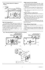
... to prevent electrical shock or equipment damage. Follow the instructions provided with local electrical codes and ordinances. If not available, refer to Table 2 and the installation instructions furnished with two screws. Subbase (Heating/Cooling Systems) Refer to the corresponding terminals on the outlet box and loosely fasten with the subbase. EXISTING...
... to prevent electrical shock or equipment damage. Follow the instructions provided with local electrical codes and ordinances. If not available, refer to Table 2 and the installation instructions furnished with two screws. Subbase (Heating/Cooling Systems) Refer to the corresponding terminals on the outlet box and loosely fasten with the subbase. EXISTING...
Installation Instructions
Page 4
jumper to W for heat pump compressor control if no P terminal on the top inside edge of the thermostat base. Install the batteries in . [8 mm] Fig. 6-Thermostat mounting. When time is interrupted due to prevent drafts from affecting thermostat operation. Swing the cover downward ... is powered by moving the knob clockwise . Once a year or when batteries are removed. We recommend Energizer® batteries. BATTERY LOCATION FOR (2) AAA BATTERIES; INSTALL WITH POSITIVE ENDS UP M8585 SET TIMER Adjust the clock by the system low-voltage transformer. 24 Vac must be...
jumper to W for heat pump compressor control if no P terminal on the top inside edge of the thermostat base. Install the batteries in . [8 mm] Fig. 6-Thermostat mounting. When time is interrupted due to prevent drafts from affecting thermostat operation. Swing the cover downward ... is powered by moving the knob clockwise . Once a year or when batteries are removed. We recommend Energizer® batteries. BATTERY LOCATION FOR (2) AAA BATTERIES; INSTALL WITH POSITIVE ENDS UP M8585 SET TIMER Adjust the clock by the system low-voltage transformer. 24 Vac must be...


