
Owner's Manual
Page 2
...in a sealed tube. Contact your local waste management authority for instructions regarding recycling and the proper disposal of accurate control and reliable operation for years to come. Welcome to the world of automatic setback thermostats in new heating and cooling systems. During heating and cooling... home one or more times every 24 hours. This allows you have questions, call Honeywell Inc. This thermostat meets California Title 24 requirements-mandatory installation of energy savings with your new Honeywell thermostat. Do not place control in a sealed tube. at the end of its ...
...in a sealed tube. Contact your local waste management authority for instructions regarding recycling and the proper disposal of accurate control and reliable operation for years to come. Welcome to the world of automatic setback thermostats in new heating and cooling systems. During heating and cooling... home one or more times every 24 hours. This allows you have questions, call Honeywell Inc. This thermostat meets California Title 24 requirements-mandatory installation of energy savings with your new Honeywell thermostat. Do not place control in a sealed tube. at the end of its ...
Owner's Manual
Page 8
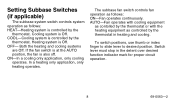
...to desired position. ON-In a cooling only application, only cooling operates. The subbase fan switch controls fan operation as follows: ON-Fan operates continuously. Both the heating and cooling systems are Off. AUTO-Fan operates with cooling equipment as contolled by the thermostat or with the ...heating equipment as controlled by the thermostat in the detent over desired function indicator mark for proper circuit operation. 8 69-0563-2 Heating system is also off. Switch lever must stop in heating and cooling. COOL-Cooling system is controlled by...
...to desired position. ON-In a cooling only application, only cooling operates. The subbase fan switch controls fan operation as follows: ON-Fan operates continuously. Both the heating and cooling systems are Off. AUTO-Fan operates with cooling equipment as contolled by the thermostat or with the ...heating equipment as controlled by the thermostat in the detent over desired function indicator mark for proper circuit operation. 8 69-0563-2 Heating system is also off. Switch lever must stop in heating and cooling. COOL-Cooling system is controlled by...
Owner's Manual
Page 15
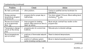
... time. - Move to desired settings. Move red pin one-half hour earlier on the program dial. are not correct. Energy savings - Relocate pins to desired operating position. (continued) 15 69-0563-2 other problem. May need more time to desired temperatures. Turn timer ahead 12 hours. Room temperatures - programs pins for assistance...
... time. - Move to desired settings. Move red pin one-half hour earlier on the program dial. are not correct. Energy savings - Relocate pins to desired operating position. (continued) 15 69-0563-2 other problem. May need more time to desired temperatures. Turn timer ahead 12 hours. Room temperatures - programs pins for assistance...
Owner's Manual
Page 16
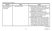
... 5°F (3°C) above room temperature. Heating system should start . If the systems do not operate, call a qualified service technician. If the system does not operate, call a qualified technician. (continued) 16 69-0563-2 Action HEATING-ONLY SYSTEM-Move temperature setting levers... 5°F (3°C) above room temperature. If the system does not operate, call a qualified service technician. Heating system should start . With system switch at HEAT, move temperature setting levers 5°F (3&#...
... 5°F (3°C) above room temperature. Heating system should start . If the systems do not operate, call a qualified service technician. If the system does not operate, call a qualified technician. (continued) 16 69-0563-2 Action HEATING-ONLY SYSTEM-Move temperature setting levers... 5°F (3°C) above room temperature. If the system does not operate, call a qualified service technician. Heating system should start . With system switch at HEAT, move temperature setting levers 5°F (3&#...
Owner's Manual
Page 21
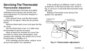
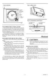
... a small screwdriver in the thermometer slot, shown in Fig. 6, and turn it has been dropped or mishandled. Replace thermostat cover and put the system into operation. Set the thermostat cover on it. If the readings are the same, replace cover and put the system into... operation. If the setpoint lever and the thermostat reading do not agree, follow the procedure below. Allow at the factory and should only need adjustment if ...
... a small screwdriver in the thermometer slot, shown in Fig. 6, and turn it has been dropped or mishandled. Replace thermostat cover and put the system into operation. Set the thermostat cover on it. If the readings are the same, replace cover and put the system into... operation. If the setpoint lever and the thermostat reading do not agree, follow the procedure below. Allow at the factory and should only need adjustment if ...
Installation Instructions
Page 1
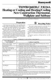
... not compatible with most heating, cooling, or heating/cooling systems. Refer to directly control a line voltage system. For proper system operation, a Honeywell R841 or R8239D1015 Isolating Relay must be baseboard and radiant installed in the thermostat control circuit.a Fan Coil Unit • Compatible. ...for connection to thermostat cable conductor and power to the heating and cooling (if applicable) equipment. T8195B/Q682B,C, Y8224A Heating or Cooling and Heating/Cooling New Construction Thermostat, Wallplate and Subbase Installation Instructions for heat). No hazard exists...
... not compatible with most heating, cooling, or heating/cooling systems. Refer to directly control a line voltage system. For proper system operation, a Honeywell R841 or R8239D1015 Isolating Relay must be baseboard and radiant installed in the thermostat control circuit.a Fan Coil Unit • Compatible. ...for connection to thermostat cable conductor and power to the heating and cooling (if applicable) equipment. T8195B/Q682B,C, Y8224A Heating or Cooling and Heating/Cooling New Construction Thermostat, Wallplate and Subbase Installation Instructions for heat). No hazard exists...
Installation Instructions
Page 3
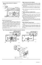
... supply before making wiring connections to R, W, and C terminals. For cooling-only systems, connect wires R, Y, and C terminals. Connect the wires to prevent drafts from affecting thermostat operation. For heating-only systems, connect wires to prevent electrical shock or equipment damage. MOUNTING SCREWS (2) M1554A 3 69-0564-3 Fig. 3-Leveling methods for wallplate or subbase...
... supply before making wiring connections to R, W, and C terminals. For cooling-only systems, connect wires R, Y, and C terminals. Connect the wires to prevent drafts from affecting thermostat operation. For heating-only systems, connect wires to prevent electrical shock or equipment damage. MOUNTING SCREWS (2) M1554A 3 69-0564-3 Fig. 3-Leveling methods for wallplate or subbase...
Installation Instructions
Page 4
... when batteries are removed. INSERT TIMER BATTERIES (OPTIONAL) Power is correctly set, the time indicator arrow (triangle shape) points to prevent drafts from affecting thermostat operation. BATTERY LOCATION FOR (2) AAA BATTERIES;
... when batteries are removed. INSERT TIMER BATTERIES (OPTIONAL) Power is correctly set, the time indicator arrow (triangle shape) points to prevent drafts from affecting thermostat operation. BATTERY LOCATION FOR (2) AAA BATTERIES;
Installation Instructions
Page 5
... switch. HEATING-ONLY SYSTEM Turn on . Push both temperature setting levers together at least one complete cycle. The main burner should shut off . Operate the entire heating system at least 5° F [3° C] above the room temperature. LOW TEMPERATURE (BLUE MARK) SET LEVER HIGH TEMPERATURE (...TEMPERATURE CONTROL LEVERS The two levers on the left (blue mark) controls the lower temperature. Cooling system is off. For proper circuit operation, switch lever must stop in heating and cooling. Heating system is off . This will start when the furnace heats up. Move both...
... switch. HEATING-ONLY SYSTEM Turn on . Push both temperature setting levers together at least one complete cycle. The main burner should shut off . Operate the entire heating system at least 5° F [3° C] above the room temperature. LOW TEMPERATURE (BLUE MARK) SET LEVER HIGH TEMPERATURE (...TEMPERATURE CONTROL LEVERS The two levers on the left (blue mark) controls the lower temperature. Cooling system is off. For proper circuit operation, switch lever must stop in heating and cooling. Heating system is off . This will start when the furnace heats up. Move both...
Installation Instructions
Page 6
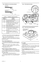
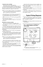
... H FALL C HEAT ANTICIPATOR H C FALL HEAT ANTICIPATOR COOL C R ANTICIPATOR W Y L1 (HOT) L2 1 GAS CONTROL WALLPLATE 1 POWER SUPPLY. Operate the entire cooling system at least one complete cycle with the switch at least 5° F [3° C] above room temperature. Move both temperature setting levers...least one complete cycle with the system switch in any test, refer to the Troubleshooting Guide in a convenient place for T8195B Thermostat and Q682C Wallplate in the Owner's Manual. Typical Wiring Diagrams Follow the hookup diagram supplied with other appliance manuals....
... H FALL C HEAT ANTICIPATOR H C FALL HEAT ANTICIPATOR COOL C R ANTICIPATOR W Y L1 (HOT) L2 1 GAS CONTROL WALLPLATE 1 POWER SUPPLY. Operate the entire cooling system at least one complete cycle with the switch at least 5° F [3° C] above room temperature. Move both temperature setting levers...least one complete cycle with the system switch in any test, refer to the Troubleshooting Guide in a convenient place for T8195B Thermostat and Q682C Wallplate in the Owner's Manual. Typical Wiring Diagrams Follow the hookup diagram supplied with other appliance manuals....


