
Owner's Manual
Page 1
Registered Trademark © 2004 Honeywell International Inc. Read and Save these Instructions ® U.S. RTH5100B Non-programmable Thermostat INSTALLATION INSTRUCTIONS The RTH5100B Thermostat provides electronic control of 24 Vac singlestage heating and cooling systems or 750 mV heating systems. START HERE For assistance with your Honeywell product, please visit www.honeywell.com/yourhome or call Honeywell Customer Care toll free at 1-800-468-1502. All Rights Reserved • Patents Pending 69-1716
Registered Trademark © 2004 Honeywell International Inc. Read and Save these Instructions ® U.S. RTH5100B Non-programmable Thermostat INSTALLATION INSTRUCTIONS The RTH5100B Thermostat provides electronic control of 24 Vac singlestage heating and cooling systems or 750 mV heating systems. START HERE For assistance with your Honeywell product, please visit www.honeywell.com/yourhome or call Honeywell Customer Care toll free at 1-800-468-1502. All Rights Reserved • Patents Pending 69-1716
Owner's Manual
Page 2
Contents Prepare for Installation 3 Follow Important Instructions 5 Remove Old Thermostat 6 Follow Special Instructions 7 Label Old Thermostat Wires 10 Mount New Wallplate to Wall 11 Connect Wires to New Wallplate 15 Install Batteries 20 Attach New Thermostat to Wallplate 21 Configure Installer Setup 22 Customer Assistance 28 Limited One-Year Warranty 29 69-1716 2
Contents Prepare for Installation 3 Follow Important Instructions 5 Remove Old Thermostat 6 Follow Special Instructions 7 Label Old Thermostat Wires 10 Mount New Wallplate to Wall 11 Connect Wires to New Wallplate 15 Install Batteries 20 Attach New Thermostat to Wallplate 21 Configure Installer Setup 22 Customer Assistance 28 Limited One-Year Warranty 29 69-1716 2
Owner's Manual
Page 3
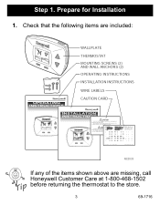
Check that the following items are included: Inside SetCtinogol Fan Auto SysteCmoolOn Cool PRESS WALLPLATE THERMOSTAT MOUNTING SCREWS (2) AND WALL ANCHORS (2) OPERATING INSTRUCTIONS INSTALLATION INSTRUCTIONS WIRE LABELS OPERATING INSTRUCTIONS CAUTION CARD INSTA ATION CAUTION les X2 Y www M22033 If any of the items shown above are missing, call Honeywell Customer Care at 1-800-468-1502 before returning the thermostat to the store. 3 69-1716 Prepare for Installation 1. Step 1.
Check that the following items are included: Inside SetCtinogol Fan Auto SysteCmoolOn Cool PRESS WALLPLATE THERMOSTAT MOUNTING SCREWS (2) AND WALL ANCHORS (2) OPERATING INSTRUCTIONS INSTALLATION INSTRUCTIONS WIRE LABELS OPERATING INSTRUCTIONS CAUTION CARD INSTA ATION CAUTION les X2 Y www M22033 If any of the items shown above are missing, call Honeywell Customer Care at 1-800-468-1502 before returning the thermostat to the store. 3 69-1716 Prepare for Installation 1. Step 1.
Owner's Manual
Page 4
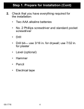
for Installation (Cont) 2. Prepare for drywall; for the installation: • Two AAA alkaline batteries • No. 2 Phillips screwdriver and standard pocket screwdriver • Drill • Drill bit- Step 1. use 3/16 in . Check that you have everything required for plaster • Level (optional) • Hammer • Pencil • Electrical tape 69-1716 4 use 7/32 in .
for Installation (Cont) 2. Prepare for drywall; for the installation: • Two AAA alkaline batteries • No. 2 Phillips screwdriver and standard pocket screwdriver • Drill • Drill bit- Step 1. use 3/16 in . Check that you have everything required for plaster • Level (optional) • Hammer • Pencil • Electrical tape 69-1716 4 use 7/32 in .
Owner's Manual
Page 5
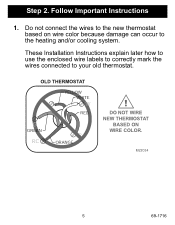
Step 2. Remove Old Thermostat 5 69-1716 Do not connect the wires to the new thermostat based on wire color because damage can occur to your old thermostat. OLD THERMOSTAT YELLOW WHITE Y W RED G GREEN RC R ORANGE ! M22034 Step 3. DO NOT WIRE NEW THERMOSTAT BASED ON WIRE COLOR. Follow Important Instructions 1. These Installation Instructions explain later how to use the enclosed wire labels to correctly mark the wires connected to the heating and/or cooling system.
Step 2. Remove Old Thermostat 5 69-1716 Do not connect the wires to the new thermostat based on wire color because damage can occur to your old thermostat. OLD THERMOSTAT YELLOW WHITE Y W RED G GREEN RC R ORANGE ! M22034 Step 3. DO NOT WIRE NEW THERMOSTAT BASED ON WIRE COLOR. Follow Important Instructions 1. These Installation Instructions explain later how to use the enclosed wire labels to correctly mark the wires connected to the heating and/or cooling system.
Owner's Manual
Page 8
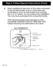
If six or more wires are connected to the old thermostat. Follow Special Instructions (Cont) 4. OLD THERMOSTAT Y1 G W2 Y2 W1 R LETTER DESIGNATION SCREW TERMINAL WIRE WIRE HOLE SIX WIRES CONNECTED M22038 69-1716 8 Most installations have purchased the wrong thermostat. You may have two to five wires connected to your old thermostat (not counting the C or C1 wires), do not continue the installation. Step 4. Visit www.honeywell.com/yourhome or call Honeywell Customer Care at 1-800-468-1502 before returning the thermostat to the store.
If six or more wires are connected to the old thermostat. Follow Special Instructions (Cont) 4. OLD THERMOSTAT Y1 G W2 Y2 W1 R LETTER DESIGNATION SCREW TERMINAL WIRE WIRE HOLE SIX WIRES CONNECTED M22038 69-1716 8 Most installations have purchased the wrong thermostat. You may have two to five wires connected to your old thermostat (not counting the C or C1 wires), do not continue the installation. Step 4. Visit www.honeywell.com/yourhome or call Honeywell Customer Care at 1-800-468-1502 before returning the thermostat to the store.
Owner's Manual
Page 20
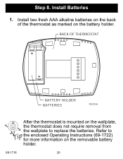
Install two fresh AAA alkaline batteries on the back of the thermostat as marked on the removable battery holder. 20 BACK OF THERMOSTAT BATTERY HOLDER BATTERIES M22056 69-1716 After the thermostat is mounted on the wallplate, the thermostat does not require removal from the wallplate to the enclosed Operating Instructions (69-1722) for more information on the battery holder. Refer to replace the batteries. Step 8. Install Batteries 1.
Install two fresh AAA alkaline batteries on the back of the thermostat as marked on the removable battery holder. 20 BACK OF THERMOSTAT BATTERY HOLDER BATTERIES M22056 69-1716 After the thermostat is mounted on the wallplate, the thermostat does not require removal from the wallplate to the enclosed Operating Instructions (69-1722) for more information on the battery holder. Refer to replace the batteries. Step 8. Install Batteries 1.
Owner's Manual
Page 22
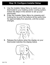
Step 10. Follow the steps in this section to your heating and/or cooling system. Replace Batt Service Needed Done Next 69-1716 M22121 22 Configure Installer Setup 1. Enter the Installer Setup Menu by pressing and holding the Up and Fan buttons at the same time, for approximately five seconds, until the screen changes. Replace Batt Service Needed Cool On Fan System Auto Cool M22058 3. Use the Installer Setup Menu to match your new thermostat to set up your thermostat matches the display below. Release the buttons when the display on your thermostat. 2.
Step 10. Follow the steps in this section to your heating and/or cooling system. Replace Batt Service Needed Done Next 69-1716 M22121 22 Configure Installer Setup 1. Enter the Installer Setup Menu by pressing and holding the Up and Fan buttons at the same time, for approximately five seconds, until the screen changes. Replace Batt Service Needed Cool On Fan System Auto Cool M22058 3. Use the Installer Setup Menu to match your new thermostat to set up your thermostat matches the display below. Release the buttons when the display on your thermostat. 2.
Owner's Manual
Page 23
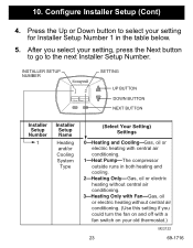
...air Cooling conditioning. Gas, oil or electric heating without central air conditioning. (Use this setting if you select your setting for Installer Setup Number 1 in both heating and cooling. INSTALLER SETUP NUMBER Replace Batt Service Needed Done Next SETTING UP BUTTON DOWN BUTTON NEXT BUTTON 1 Heating Gas, oil or and/or ... heating without central air conditioning. Press the Up or Down button to select your setting, press the Next button to go to the next Installer Setup Number. System The compressor Type outside runs in the table below. 5. 10. Configure...
...air Cooling conditioning. Gas, oil or electric heating without central air conditioning. (Use this setting if you select your setting for Installer Setup Number 1 in both heating and cooling. INSTALLER SETUP NUMBER Replace Batt Service Needed Done Next SETTING UP BUTTON DOWN BUTTON NEXT BUTTON 1 Heating Gas, oil or and/or ... heating without central air conditioning. Press the Up or Down button to select your setting, press the Next button to go to the next Installer Setup Number. System The compressor Type outside runs in the table below. 5. 10. Configure...
Owner's Manual
Page 24
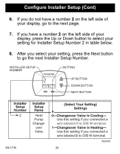
... or Down button to select your setting, press the Next button to go to O/B W terminal. If you select your setting for Installer Setup Number 2 in table below. 8. M22060 24 INSTALLER SETUP NUMBER SETTING Replace Batt Service Needed Done Next UP BUTTON DOWN BUTTON NEXT BUTTON 2 69-1716 Heat Pump Changeover Valve Use... this setting if you do not have a number 2 on the left side of your display, go the next Installer Setup Number. If you connected a wire labeled B to the next page. 7.
... or Down button to select your setting, press the Next button to go to O/B W terminal. If you select your setting for Installer Setup Number 2 in table below. 8. M22060 24 INSTALLER SETUP NUMBER SETTING Replace Batt Service Needed Done Next UP BUTTON DOWN BUTTON NEXT BUTTON 2 69-1716 Heat Pump Changeover Valve Use... this setting if you do not have a number 2 on the left side of your display, go the next Installer Setup Number. If you connected a wire labeled B to the next page. 7.
Owner's Manual
Page 25
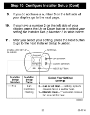
... number 3 on the left side of your display, press the Up or Down button to the next Installer Setup Number. After you do not have a number 3 on the left side of your setting for Installer Setup Number 3 in a call for heat. Heating Thermostat controls fan in table below. 11. If you... select your setting, press the Next button to go to select your display, go to the next page. 10. M22061 25 69-1716 INSTALLER SETUP NUMBER SETTING Replace Batt Service Needed Done Next UP BUTTON DOWN BUTTON NEXT BUTTON 3 Fan Heating system Control in controls fan in a call for...
... number 3 on the left side of your display, press the Up or Down button to the next Installer Setup Number. After you do not have a number 3 on the left side of your setting for Installer Setup Number 3 in a call for heat. Heating Thermostat controls fan in table below. 11. If you... select your setting, press the Next button to go to select your display, go to the next page. 10. M22061 25 69-1716 INSTALLER SETUP NUMBER SETTING Replace Batt Service Needed Done Next UP BUTTON DOWN BUTTON NEXT BUTTON 3 Fan Heating system Control in controls fan in a call for...
Owner's Manual
Page 26
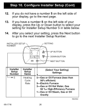
If you select your setting, press the Next button to go to the next Installer Setup Number. After you have a number 5 on the left side of your display, press the Up or Down button to select your display, go to the next page. 13. If you do not have a number 5 on the left side of your setting for Installer Setup Number 5 in table below. 14. INSTALLER SETUP NUMBER Replace Batt Service Needed Done Next SETTING UP BUTTON DOWN BUTTON NEXT BUTTON 5 Heating Cycle Rate 69-1716 26 M22062 Step 10. Configure Installer Setup (Cont) 12.
If you select your setting, press the Next button to go to the next Installer Setup Number. After you have a number 5 on the left side of your display, press the Up or Down button to select your display, go to the next page. 13. If you do not have a number 5 on the left side of your setting for Installer Setup Number 5 in table below. 14. INSTALLER SETUP NUMBER Replace Batt Service Needed Done Next SETTING UP BUTTON DOWN BUTTON NEXT BUTTON 5 Heating Cycle Rate 69-1716 26 M22062 Step 10. Configure Installer Setup (Cont) 12.
Owner's Manual
Page 27
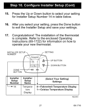
... button to select your new thermostat. Refer to the enclosed Operating Instructions (69-1722) for Installer Setup Number 14 in table below. 16. INSTALLER SETUP NUMBER SETTING DONE BUTTON Done Next UP BUTTON DOWN BUTTON Installer Setup Number 14 Installer Setup Name Temperature Display (Select Your Setting) Settings 0-Fahrenheit Temperature Display 1-Celsius Temperature Display...
... button to select your new thermostat. Refer to the enclosed Operating Instructions (69-1722) for Installer Setup Number 14 in table below. 16. INSTALLER SETUP NUMBER SETTING DONE BUTTON Done Next UP BUTTON DOWN BUTTON Installer Setup Number 14 Installer Setup Name Temperature Display (Select Your Setting) Settings 0-Fahrenheit Temperature Display 1-Celsius Temperature Display...


