Installation Instructions
Page 1
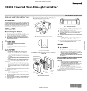
...and pulling the assembly out of Humidifier HE365 Powered Flow-Through Humidifier READ AND SAVE THESE INSTRUCTIONS APPLICATION The HE365 Powered Flow-Through Humidifier works with applicable local codes, ordinances and regulations. CAUTION Hazardous Voltage. Remove the humidifier pad assembly by the Honeywell Perfect Climate Comfort Center™ control...in the hole (be sure the template is no greater than 0.4 in the instructions and on the bottom of fan centers include humidifer taps so the current sensing relay or sail switch is facing up. Secure the housing with ...
...and pulling the assembly out of Humidifier HE365 Powered Flow-Through Humidifier READ AND SAVE THESE INSTRUCTIONS APPLICATION The HE365 Powered Flow-Through Humidifier works with applicable local codes, ordinances and regulations. CAUTION Hazardous Voltage. Remove the humidifier pad assembly by the Honeywell Perfect Climate Comfort Center™ control...in the hole (be sure the template is no greater than 0.4 in the instructions and on the bottom of fan centers include humidifer taps so the current sensing relay or sail switch is facing up. Secure the housing with ...

Installation Instructions
Page 2
...Honeywell International Inc. Template (entire sheet) Top of the solenoid valve. M12686A Fig. 5. PROVIDE DISCONNECT MEANS AND OVERLOAD PROTECTION AS REQUIRED. 2 24V WIRING. M12684A Fig. 6. Typical wiring diagram of sail switch with humidifier. MECHANICAL HUMIDISTAT 2 HUMIDIFIER 120 VAC 1 SAIL SWITCH YELLOW WIRES 1 POWER.... NOTE: Lightly clean the copper tubing ends with the Automatic Humidity Control. • Use 18-22 gauge insulated wire for frost and HVAC fan operation. HVAC TrueIAQ R CWY G HUM YELLOW HUM R C W G 1 R Rc W Y G THERMOSTAT 1 If a thermostat other than...
...Honeywell International Inc. Template (entire sheet) Top of the solenoid valve. M12686A Fig. 5. PROVIDE DISCONNECT MEANS AND OVERLOAD PROTECTION AS REQUIRED. 2 24V WIRING. M12684A Fig. 6. Typical wiring diagram of sail switch with humidifier. MECHANICAL HUMIDISTAT 2 HUMIDIFIER 120 VAC 1 SAIL SWITCH YELLOW WIRES 1 POWER.... NOTE: Lightly clean the copper tubing ends with the Automatic Humidity Control. • Use 18-22 gauge insulated wire for frost and HVAC fan operation. HVAC TrueIAQ R CWY G HUM YELLOW HUM R C W G 1 R Rc W Y G THERMOSTAT 1 If a thermostat other than...

Owners Manual
Page 1
HE360A,B Powered Flow-Through Humidifier INSTALLATION GUIDE/OWNER'S MANUAL 69-1176-04
HE360A,B Powered Flow-Through Humidifier INSTALLATION GUIDE/OWNER'S MANUAL 69-1176-04

Owners Manual
Page 2
HE360A,B POWERED FLOW-THROUGH HUMIDIFIER 69-1176-04 2
HE360A,B POWERED FLOW-THROUGH HUMIDIFIER 69-1176-04 2

Owners Manual
Page 3
...POWERED FLOW-THROUGH HUMIDIFIER WELCOME To the comfortable world of your home. APPLICATION This kit contains your home. You have also taken the first step in improving the comfort of humidified air. Your humidity control monitors the relative humidity and activates the humidifier accordingly. Congratulations! As the vapor circulates, the relative humidity rises. Humidified... the zapping you create when you use your Honeywell humidifier, notice that humidified air makes. The end result is created when warm air blows over a humidifier pad. The warm dry air, from the ...
...POWERED FLOW-THROUGH HUMIDIFIER WELCOME To the comfortable world of your home. APPLICATION This kit contains your home. You have also taken the first step in improving the comfort of humidified air. Your humidity control monitors the relative humidity and activates the humidifier accordingly. Congratulations! As the vapor circulates, the relative humidity rises. Humidified... the zapping you create when you use your Honeywell humidifier, notice that humidified air makes. The end result is created when warm air blows over a humidifier pad. The warm dry air, from the ...
Owners Manual
Page 4
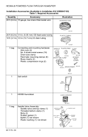
... wire Illustration THERMOSTAT WIRE 20 ft (6.2m) 1/4 in. (6.35 mm) OD feed water tubing 10 ft (3.1m) 1/2 in Installation Kit 32005847-00) Table 1. HE360A,B POWERED FLOW-THROUGH HUMIDIFIER Installation Accessories (Available in (12.7 mm) ID drain tubing M31006 PLASTIC TUBING 1 bag Connecting and mounting hardware: Wire nuts (4) No. 8 sheet metal screws (18...
... wire Illustration THERMOSTAT WIRE 20 ft (6.2m) 1/4 in. (6.35 mm) OD feed water tubing 10 ft (3.1m) 1/2 in Installation Kit 32005847-00) Table 1. HE360A,B POWERED FLOW-THROUGH HUMIDIFIER Installation Accessories (Available in (12.7 mm) ID drain tubing M31006 PLASTIC TUBING 1 bag Connecting and mounting hardware: Wire nuts (4) No. 8 sheet metal screws (18...

Owners Manual
Page 5
HE360A,B POWERED FLOW-THROUGH HUMIDIFIER Required Tools Tools required for installation include: • Tin snips. • Screwdriver. • Adjustable or open-end wrench. • Battery-powered Drill, punch or awl. • Level. • Work Gloves (preferably cut-resistant). • Safety Glasses. 5 69-1176-04
HE360A,B POWERED FLOW-THROUGH HUMIDIFIER Required Tools Tools required for installation include: • Tin snips. • Screwdriver. • Adjustable or open-end wrench. • Battery-powered Drill, punch or awl. • Level. • Work Gloves (preferably cut-resistant). • Safety Glasses. 5 69-1176-04
Owners Manual
Page 6
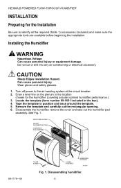
.... CAUTION Sharp Edges Installation Hazard. Draw a level line on the plenum in the box). 4. Disassemble the humidifier; Remove the template and carefully cut or drill into any air conditioning or electrical accessory. Turn off power to identify all the required (Table 1) accessories (included) and make sure the appropriate tools are available before...
.... CAUTION Sharp Edges Installation Hazard. Draw a level line on the plenum in the box). 4. Disassemble the humidifier; Remove the template and carefully cut or drill into any air conditioning or electrical accessory. Turn off power to identify all the required (Table 1) accessories (included) and make sure the appropriate tools are available before...

Owners Manual
Page 7
HE360A,B POWERED FLOW-THROUGH HUMIDIFIER • Select a location that cannot damage the air conditioner A-coil during installation. • Do not locate the humidifier on the furnace body. • Allow adequate ...water in the return air duct. (See Fig 2.) 7 69-1176-04 Sail switch detects when furnace fan is operating. • Select a location where the air duct is properly sensing the relative humidity of air...sail is in . (78 mm) above the humidifier so you install the Honeywell Whole House Drum or Disk Humidifier. Make sure that the 20 ft (6.2m) of an unrestricted air stream....
HE360A,B POWERED FLOW-THROUGH HUMIDIFIER • Select a location that cannot damage the air conditioner A-coil during installation. • Do not locate the humidifier on the furnace body. • Allow adequate ...water in the return air duct. (See Fig 2.) 7 69-1176-04 Sail switch detects when furnace fan is operating. • Select a location where the air duct is properly sensing the relative humidity of air...sail is in . (78 mm) above the humidifier so you install the Honeywell Whole House Drum or Disk Humidifier. Make sure that the 20 ft (6.2m) of an unrestricted air stream....

Owners Manual
Page 8
.... Can cause personal injury. CLIP CLIP M12813 Fig. 3. If not available, contact an electrician to have one installed. • Make sure that the humidifier cord is adequate to reach from the humidifier to the outlet. • Make sure that the 20 ft (6.2m) of thermostat wire is adequate to reach from the... humidifier solenoid, to the sail switch, to an outlet. CAUTION Sharp Edges Installation Hazard. Position securing clips. Position the securing clips as shown in Fig. 3. Do ...
.... Can cause personal injury. CLIP CLIP M12813 Fig. 3. If not available, contact an electrician to have one installed. • Make sure that the humidifier cord is adequate to reach from the humidifier to the outlet. • Make sure that the 20 ft (6.2m) of thermostat wire is adequate to reach from the... humidifier solenoid, to the sail switch, to an outlet. CAUTION Sharp Edges Installation Hazard. Position securing clips. Position the securing clips as shown in Fig. 3. Do ...

Owners Manual
Page 9
... the tube is level, then position it in the opening . Push in the humidifier housing. IMPORTANT Be sure to flatten cut edges. HE360A,B POWERED FLOW-THROUGH HUMIDIFIER 2. Reinstall the humidifier pad assembly in securing clips until completely seated. 4. Make sure the humidifier housing is not pinched or kinked. 6. Drill holes and install the three sheet...
... the tube is level, then position it in the opening . Push in the humidifier housing. IMPORTANT Be sure to flatten cut edges. HE360A,B POWERED FLOW-THROUGH HUMIDIFIER 2. Reinstall the humidifier pad assembly in securing clips until completely seated. 4. Make sure the humidifier housing is not pinched or kinked. 6. Drill holes and install the three sheet...

Owners Manual
Page 10
... mm) OD tubing and connect the saddle valve to an air conditioner. The valve is not designed to regulate water flow. Use 1/4 in the humidifier. 1. b. c. CAUTION Chemical Hazard. Use the self-piercing saddle valve (included) to install the saddle valve handle pointing toward the ceiling. See ... water. SCREW DRIVER WATER LINE M20175 Fig. 5. Installing the saddle valve. 3. a. Do not use gas line. 2. HE360A,B POWERED FLOW-THROUGH HUMIDIFIER Connecting the Plumbing Use hot or cold water and either open or closed. Do not use any line connected to the inlet side of...
... mm) OD tubing and connect the saddle valve to an air conditioner. The valve is not designed to regulate water flow. Use 1/4 in the humidifier. 1. b. c. CAUTION Chemical Hazard. Use the self-piercing saddle valve (included) to install the saddle valve handle pointing toward the ceiling. See ... water. SCREW DRIVER WATER LINE M20175 Fig. 5. Installing the saddle valve. 3. a. Do not use gas line. 2. HE360A,B POWERED FLOW-THROUGH HUMIDIFIER Connecting the Plumbing Use hot or cold water and either open or closed. Do not use any line connected to the inlet side of...
Owners Manual
Page 11
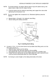
...BRASS COMPRESSION NUT PLASTIC COMPRESSION RING BRASS INSERT M20176 Fig. 6. c. ment and ensure downward slope for solenoid valve fitting. HE360A,B POWERED FLOW-THROUGH HUMIDIFIER NOTE: To prevent leaking, use duct tape) along the route to correct length so the tubing terminates at the drain. 11 ...clamp around the tubing to the floor drain (see Fig. 7). Installing feed tubing. 4. Push the tubing over the drain nipple on the humidifier. Use copper sleeve rings only with copper tubing. a. b. d. NOTE: Cut tubing to prevent move- Fasten the drain tubing (can use ...
...BRASS COMPRESSION NUT PLASTIC COMPRESSION RING BRASS INSERT M20176 Fig. 6. c. ment and ensure downward slope for solenoid valve fitting. HE360A,B POWERED FLOW-THROUGH HUMIDIFIER NOTE: To prevent leaking, use duct tape) along the route to correct length so the tubing terminates at the drain. 11 ...clamp around the tubing to the floor drain (see Fig. 7). Installing feed tubing. 4. Push the tubing over the drain nipple on the humidifier. Use copper sleeve rings only with copper tubing. a. b. d. NOTE: Cut tubing to prevent move- Fasten the drain tubing (can use ...

Owners Manual
Page 12
These springs offset the effect of gravity for installation. 69-1176-04 12 IMPORTANT: Do not use the sail switch with both springs attached. HE360A,B POWERED FLOW-THROUGH HUMIDIFIER M20177 Fig. 7. Installing the Sail Switch Adapting Switch to select air flow direction and remove spring(s) not required for air flow direction. Installing the drain tubing. Be sure to Air Flow Direction The S688A Sail Switch has two counterbalancing springs in place as shown in Fig 8.
These springs offset the effect of gravity for installation. 69-1176-04 12 IMPORTANT: Do not use the sail switch with both springs attached. HE360A,B POWERED FLOW-THROUGH HUMIDIFIER M20177 Fig. 7. Installing the Sail Switch Adapting Switch to select air flow direction and remove spring(s) not required for air flow direction. Installing the drain tubing. Be sure to Air Flow Direction The S688A Sail Switch has two counterbalancing springs in place as shown in Fig 8.

Owners Manual
Page 13
... attached to the bracket marked Down. Center punch the screw holes indicated and drill out with the sail switch) at the desired location. HE360A,B POWERED FLOW-THROUGH HUMIDIFIER UP M3014 Fig. 8. Adapting sail switch to air flow direction or mounting position. • Vertical downward air flow: Leave the spring in Fig 9. 13...
... attached to the bracket marked Down. Center punch the screw holes indicated and drill out with the sail switch) at the desired location. HE360A,B POWERED FLOW-THROUGH HUMIDIFIER UP M3014 Fig. 8. Adapting sail switch to air flow direction or mounting position. • Vertical downward air flow: Leave the spring in Fig 9. 13...

Owners Manual
Page 14
LOOSEN SETSCREW - HE360A,B POWERED FLOW-THROUGH HUMIDIFIER - Attaching sail to switch. 5. TUCK CORD INTO TAB SLOTS - INSERT SAIL CORD - Press together the sides of airflow. 69-1176-04 14 Inserting sail switch in Fig.10.) AIRFLOW M20178 Fig. 10. Insert the sail into the duct. (When in the Off position, the sail should point into the direction of airflow as shown in direction of the wire loop. TIGHTEN SETSCREW SAIL M31017 Fig. 9.
LOOSEN SETSCREW - HE360A,B POWERED FLOW-THROUGH HUMIDIFIER - Attaching sail to switch. 5. TUCK CORD INTO TAB SLOTS - INSERT SAIL CORD - Press together the sides of airflow. 69-1176-04 14 Inserting sail switch in Fig.10.) AIRFLOW M20178 Fig. 10. Insert the sail into the duct. (When in the Off position, the sail should point into the direction of airflow as shown in direction of the wire loop. TIGHTEN SETSCREW SAIL M31017 Fig. 9.

Owners Manual
Page 15
... location chosen for the H8908. 3. Humidistat base and rear view. 15 69-1176-04 NOTE: For wall mounting instructions, see the H8908 Installation Instructions. HE360A,B POWERED FLOW-THROUGH HUMIDIFIER 6. After wiring, snap on Mounting Duct 1.
... location chosen for the H8908. 3. Humidistat base and rear view. 15 69-1176-04 NOTE: For wall mounting instructions, see the H8908 Installation Instructions. HE360A,B POWERED FLOW-THROUGH HUMIDIFIER 6. After wiring, snap on Mounting Duct 1.

Owners Manual
Page 16
... both ends for connections. HE360A,B POWERED FLOW-THROUGH HUMIDIFIER WIRING CAUTION Hazardous Voltage. Wire the humidifier solenoid valve, sail switch, humidistat and transformer.See Fig. 12. At the humidifier, connect the black and white conductors to the two yellow humidifier wires. (The red wires from ... 4. At the sail switch, connect the black and white conductors to the humidistat, and from the humidifier are not used ). 69-1176-04 16 Disconnect power supply before installing or servicing equipment. Wiring the controls. 1. Cut lengths of thermostat wire to reach between...
... both ends for connections. HE360A,B POWERED FLOW-THROUGH HUMIDIFIER WIRING CAUTION Hazardous Voltage. Wire the humidifier solenoid valve, sail switch, humidistat and transformer.See Fig. 12. At the humidifier, connect the black and white conductors to the two yellow humidifier wires. (The red wires from ... 4. At the sail switch, connect the black and white conductors to the humidistat, and from the humidifier are not used ). 69-1176-04 16 Disconnect power supply before installing or servicing equipment. Wiring the controls. 1. Cut lengths of thermostat wire to reach between...
Owners Manual
Page 17
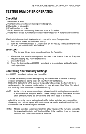
... following steps to 10ºF (6ºC) above room temperature. Turn on the heat by setting the thermostat to check the humidifier operation: 1. Make sure that can cause excessive levels of humidity that water is recommended to accommodate dewpoint effects. Reset the ..., set the humidity control to the lowest setting to turn on the power and the water supply 2. NOTE: If these activities persist for leaks. 5. HE360A,B POWERED FLOW-THROUGH HUMIDIFIER TESTING HUMIDIFIER OPERATION Checklist ‰ Humidifier is level. ‰ Control wiring was reviewed using the combination of relative...
... following steps to 10ºF (6ºC) above room temperature. Turn on the heat by setting the thermostat to check the humidifier operation: 1. Make sure that can cause excessive levels of humidity that water is recommended to accommodate dewpoint effects. Reset the ..., set the humidity control to the lowest setting to turn on the power and the water supply 2. NOTE: If these activities persist for leaks. 5. HE360A,B POWERED FLOW-THROUGH HUMIDIFIER TESTING HUMIDIFIER OPERATION Checklist ‰ Humidifier is level. ‰ Control wiring was reviewed using the combination of relative...

Owners Manual
Page 18
HE360A,B POWERED FLOW-THROUGH HUMIDIFIER Table 2. Setting Your Humidistat. When Outside Temperature is: Use This Control Setting: -20°F (-29°C) 15 -10°F (-23°C) 20 0°F (-18°C) 25 +10°F (-12°C) 30 +20°F (-7°C) 35 Above 20°F (-7°C) 40 69-1176-04 18
HE360A,B POWERED FLOW-THROUGH HUMIDIFIER Table 2. Setting Your Humidistat. When Outside Temperature is: Use This Control Setting: -20°F (-29°C) 15 -10°F (-23°C) 20 0°F (-18°C) 25 +10°F (-12°C) 30 +20°F (-7°C) 35 Above 20°F (-7°C) 40 69-1176-04 18


