
Owner's Manual
Page 1
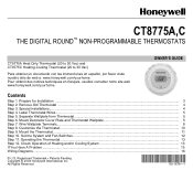
... Check Operation of Heating and/or Cooling System 13 If You Have A Problem ...15 Wiring Diagrams...16 ® U.S. Registered Trademark • Patents Pending Copyright © 2004 Honeywell International Inc. Wire Wallplate Terminals...8 Step 8. All Rights Reserved 69-1676-1 Set the System and Fan Switches...consulter notre site web www.honeywell.com/yourhome. Mount Decorator Cover Plate and Thermostat Wallplate 5 Step 7. CT8775A,C THE DIGITAL ROUND™ NON-PROGRAMMABLE THERMOSTATS CT8775A Heat Only Thermostat (20 to 30 Vac) and CT8775C Heating-Cooling Thermostat (20 ...
... Check Operation of Heating and/or Cooling System 13 If You Have A Problem ...15 Wiring Diagrams...16 ® U.S. Registered Trademark • Patents Pending Copyright © 2004 Honeywell International Inc. Wire Wallplate Terminals...8 Step 8. All Rights Reserved 69-1676-1 Set the System and Fan Switches...consulter notre site web www.honeywell.com/yourhome. Mount Decorator Cover Plate and Thermostat Wallplate 5 Step 7. CT8775A,C THE DIGITAL ROUND™ NON-PROGRAMMABLE THERMOSTATS CT8775A Heat Only Thermostat (20 to 30 Vac) and CT8775C Heating-Cooling Thermostat (20 ...
Owner's Manual
Page 8
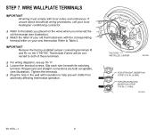
... of these terminals. ❑ For wiring diagrams, see illustration). FOR WRAPAROUND INSERTION STRIP 7/16 IN. (11 MM). If unsure about household wiring procedures, call your new thermostat. Wraparound and straight connections are both of your old thermostat wire with insulation to help prevent drafts from... terminal. Tighten the terminals. ❑ Plug the hole in the wall with the corresponding W terminal letter on the CT8775C Thermostat if wires will be connected to Table 2. IMPORTANT Remove the factory-installed jumper connecting terminals R and Rc on your local R ...
... of these terminals. ❑ For wiring diagrams, see illustration). FOR WRAPAROUND INSERTION STRIP 7/16 IN. (11 MM). If unsure about household wiring procedures, call your new thermostat. Wraparound and straight connections are both of your old thermostat wire with insulation to help prevent drafts from... terminal. Tighten the terminals. ❑ Plug the hole in the wall with the corresponding W terminal letter on the CT8775C Thermostat if wires will be connected to Table 2. IMPORTANT Remove the factory-installed jumper connecting terminals R and Rc on your local R ...
Owner's Manual
Page 15
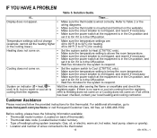
...Table 5. Solution Guide. or the cooling lower). 45 to 99°F (7 to www.honeywell.com/yourhome or call Honeywell Customer Care, toll free, at the equipment is in the Off position. System on . ...Off position. • Wait five minutes for heating. Refer to Table 2 or the wiring diagrams. • Make sure the thermostat is mounted and latched on back of heating/cooling ...Off position. • Wait five minutes for the system to 32°C) for the system to Cool (CT8775C only). • Make sure the temperature setting is below model number). • Type of thermostat). &#...
...Table 5. Solution Guide. or the cooling lower). 45 to 99°F (7 to www.honeywell.com/yourhome or call Honeywell Customer Care, toll free, at the equipment is in the Off position. System on . ...Off position. • Wait five minutes for heating. Refer to Table 2 or the wiring diagrams. • Make sure the thermostat is mounted and latched on back of heating/cooling ...Off position. • Wait five minutes for the system to 32°C) for the system to Cool (CT8775C only). • Make sure the temperature setting is below model number). • Type of thermostat). &#...
Owner's Manual
Page 16
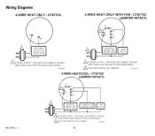
M19451 69-1676-1 O B 2 Rc G R Y W 1 HEATING COMPRESSOR FAN RELAY OR VALVE COIL CONTACTOR RELAY 1 POWER SUPPLY. M19452 16 PROVIDE DISCONNECT MEANS AND OVERLOAD PROTECTION AS REQUIRED. 2 FACTORY INSTALLED JUMPER. PROVIDE DISCONNECT MEANS AND OVERLOAD PROTECTION AS REQUIRED. M19450 O B Rc 2 G R Y W 1 HEATING RELAY OR VALVE COIL FAN RELAY 1 POWER SUPPLY. Wiring Diagrams R W 1 HEATING RELAY OR VALVE COIL 1 POWER SUPPLY. PROVIDE DISCONNECT MEANS AND OVERLOAD PROTECTION AS REQUIRED. 2 FACTORY INSTALLED JUMPER.
M19451 69-1676-1 O B 2 Rc G R Y W 1 HEATING COMPRESSOR FAN RELAY OR VALVE COIL CONTACTOR RELAY 1 POWER SUPPLY. M19452 16 PROVIDE DISCONNECT MEANS AND OVERLOAD PROTECTION AS REQUIRED. 2 FACTORY INSTALLED JUMPER. PROVIDE DISCONNECT MEANS AND OVERLOAD PROTECTION AS REQUIRED. M19450 O B Rc 2 G R Y W 1 HEATING RELAY OR VALVE COIL FAN RELAY 1 POWER SUPPLY. Wiring Diagrams R W 1 HEATING RELAY OR VALVE COIL 1 POWER SUPPLY. PROVIDE DISCONNECT MEANS AND OVERLOAD PROTECTION AS REQUIRED. 2 FACTORY INSTALLED JUMPER.


