
Owner's Manual
Page 1
... Heat Only Thermostat (20 to 30 Vac) and CT8775C Heating-Cooling Thermostat (20 to 30 Vac) Para obtener un documento con las instrucciones en español, por favor visite nuestro sitio de web a: www.honeywell.com/yourhome. Mount Decorator Cover Plate and Thermostat Wallplate...of Heating and/or Cooling System 13 If You Have A Problem ...15 Wiring Diagrams...16 ® U.S. Set the System and Fan Switches ...12 Step 11. Registered Trademark • Patents Pending Copyright © 2004 Honeywell International Inc. Prepare for Installation ...3 Step 2. Pour obtenir des notices techniques...
... Heat Only Thermostat (20 to 30 Vac) and CT8775C Heating-Cooling Thermostat (20 to 30 Vac) Para obtener un documento con las instrucciones en español, por favor visite nuestro sitio de web a: www.honeywell.com/yourhome. Mount Decorator Cover Plate and Thermostat Wallplate...of Heating and/or Cooling System 13 If You Have A Problem ...15 Wiring Diagrams...16 ® U.S. Set the System and Fan Switches ...12 Step 11. Registered Trademark • Patents Pending Copyright © 2004 Honeywell International Inc. Prepare for Installation ...3 Step 2. Pour obtenir des notices techniques...
Owner's Manual
Page 3
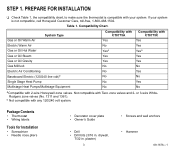
...CT8775C Yes Yes Yesa Yes Yes No Yes No Yes No aCompatible with Taco zone valves and 2- drywall, 7/32 in . PREPARE FOR INSTALLATION ❑ Check Table 1, the compatibility chart, to make sure the thermostat is not compatible, call Honeywell Customer Care, toll-free, 1-800-468-1502. STEP 1. Not compatible with 2-wire Honeywell... zone valves. If your system is compatible with any 120/240 volt system. or 3-wire WhiteRodgers zone valves (No. 1311...
...CT8775C Yes Yes Yesa Yes Yes No Yes No Yes No aCompatible with Taco zone valves and 2- drywall, 7/32 in . PREPARE FOR INSTALLATION ❑ Check Table 1, the compatibility chart, to make sure the thermostat is not compatible, call Honeywell Customer Care, toll-free, 1-800-468-1502. STEP 1. Not compatible with 2-wire Honeywell... zone valves. If your system is compatible with any 120/240 volt system. or 3-wire WhiteRodgers zone valves (No. 1311...
Owner's Manual
Page 4
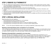
...C or C1 terminals), you have a multistage heat pump or other multistage system. Place the wires where they work properly. This thermostat is connected to six or more wires (excluding wires connected to the wallplate and lift the thermostat away. REMOVE OLD THERMOSTAT ❑ Test your ...the cooling system when outdoor temperature is connected to three wires on a warm air heating only system. • A thermostat that may have either system does not work with these systems, return the product to your system, call Honeywell Customer Care, at 1-800-468-1502. 69-1676...
...C or C1 terminals), you have a multistage heat pump or other multistage system. Place the wires where they work properly. This thermostat is connected to six or more wires (excluding wires connected to the wallplate and lift the thermostat away. REMOVE OLD THERMOSTAT ❑ Test your ...the cooling system when outdoor temperature is connected to three wires on a warm air heating only system. • A thermostat that may have either system does not work with these systems, return the product to your system, call Honeywell Customer Care, at 1-800-468-1502. 69-1676...
Owner's Manual
Page 5
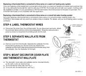
...thermostat that is connected to three wires on a zoned hot water ... COVER REMOVED THERMOSTAT WALL PLATE STEP 6. STEP 4. Wrap the wires around a pencil as shown to keep them from the old...to three wires on a warm air heating only system If you are replacing a thermostat that is connected to three wires on ...onto an electrical box, see Fig. 2. 5 M19492 69-1676-1 WIRES THROUGH WALL OPENING STEP 5. Continue with your local heating and/or cooling... with the old terminal designation. LABEL THERMOSTAT WIRES ❑ Disconnect the wires from falling back into the wall. SEPARATE ...
...thermostat that is connected to three wires on a zoned hot water ... COVER REMOVED THERMOSTAT WALL PLATE STEP 6. STEP 4. Wrap the wires around a pencil as shown to keep them from the old...to three wires on a warm air heating only system If you are replacing a thermostat that is connected to three wires on ...onto an electrical box, see Fig. 2. 5 M19492 69-1676-1 WIRES THROUGH WALL OPENING STEP 5. Continue with your local heating and/or cooling... with the old terminal designation. LABEL THERMOSTAT WIRES ❑ Disconnect the wires from falling back into the wall. SEPARATE ...

Owner's Manual
Page 6
... holes on the left and right sides of the decorator cover plate is M19493 pointing up with the wall. ❑ Pull the wires through the wiring holes and reposition the decorator cover plate (if used) and wallplate over the decorator cover plate. Mount decorator cover plate (optional) ...and ❑ Remove the wallplate and decorator cover plate (if used ) and wallplate to the wall, pull the wires through the wiring hole on the decorator cover plate. holes where marked. Position the decorator cover plate against the wall so that the UP indicator on ...
... holes on the left and right sides of the decorator cover plate is M19493 pointing up with the wall. ❑ Pull the wires through the wiring holes and reposition the decorator cover plate (if used) and wallplate over the decorator cover plate. Mount decorator cover plate (optional) ...and ❑ Remove the wallplate and decorator cover plate (if used ) and wallplate to the wall, pull the wires through the wiring hole on the decorator cover plate. holes where marked. Position the decorator cover plate against the wall so that the UP indicator on ...
Owner's Manual
Page 7
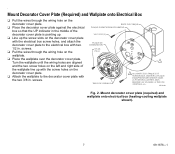
...box screw holes, and attach the decorator cover plate to the decorator cover plate with the two 3/8 in . Turn the wallplate until the wiring holes are aligned and the two screw holes on the left and right side of the decorator cover plate is pointing up. ❑ ...(heating-cooling wallplate shown). 7 69-1676-1 MF19494 Fig. 2. Mount Decorator Cover Plate (Required) and Wallplate onto Electrical Box ❑ Pull the wires through the wiring hole on the decorator cover plate. ❑ Attach the wallplate to the electrical box with the screw holes on the wallplate. ❑ Place the...
...box screw holes, and attach the decorator cover plate to the decorator cover plate with the two 3/8 in . Turn the wallplate until the wiring holes are aligned and the two screw holes on the left and right side of the decorator cover plate is pointing up. ❑ ...(heating-cooling wallplate shown). 7 69-1676-1 MF19494 Fig. 2. Mount Decorator Cover Plate (Required) and Wallplate onto Electrical Box ❑ Pull the wires through the wiring hole on the decorator cover plate. ❑ Attach the wallplate to the electrical box with the screw holes on the wallplate. ❑ Place the...
Owner's Manual
Page 8
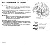
...INSTALLED JUMPER M19495 FOR STRAIGHT INSERTION STRIP 5/16 IN. (8 MM). If unsure about household wiring procedures, call your new thermostat. G ❑ Refer to the labels you placed on the wires when you removed the Y old thermostat (see illustration). ❑ Match the letter of ... terminals. ❑ Plug the hole in the wall with the corresponding W terminal letter on the CT8775C Thermostat if wires will be connected to Table 2. WIRE WALLPLATE TERMINALS IMPORTANT All wiring must comply with local codes and ordinances. FOR WRAPAROUND INSERTION STRIP 7/16 IN. (11 MM). ...
...INSTALLED JUMPER M19495 FOR STRAIGHT INSERTION STRIP 5/16 IN. (8 MM). If unsure about household wiring procedures, call your new thermostat. G ❑ Refer to the labels you placed on the wires when you removed the Y old thermostat (see illustration). ❑ Match the letter of ... terminals. ❑ Plug the hole in the wall with the corresponding W terminal letter on the CT8775C Thermostat if wires will be connected to Table 2. WIRE WALLPLATE TERMINALS IMPORTANT All wiring must comply with local codes and ordinances. FOR WRAPAROUND INSERTION STRIP 7/16 IN. (11 MM). ...
Owner's Manual
Page 9
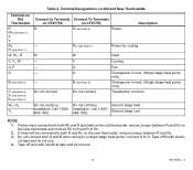
...G, F O B (see Note 3) C (see Note 4) X (see Note 4) B (see Note 3) W2, H2 Y2 Connect to Terminals Connect To Terminals on CT8775A on CT8775C R R (see Note 3) Do not connect. If wires were connected to Rc. 2. Power for cooling Heat Cooling Fan Changeover in heat. (Single stage heat pump only). Transformer common Do not... continue Do not continue Second stage heat. W - - - - If wires will be connected to both R and Rc on the new thermostat, remove jumper between R and Rc on the new thermostat and connect Rh ...
...G, F O B (see Note 3) C (see Note 4) X (see Note 4) B (see Note 3) W2, H2 Y2 Connect to Terminals Connect To Terminals on CT8775A on CT8775C R R (see Note 3) Do not connect. If wires were connected to Rc. 2. Power for cooling Heat Cooling Fan Changeover in heat. (Single stage heat pump only). Transformer common Do not... continue Do not continue Second stage heat. W - - - - If wires will be connected to both R and Rc on the new thermostat, remove jumper between R and Rc on the new thermostat and connect Rh ...
Owner's Manual
Page 15
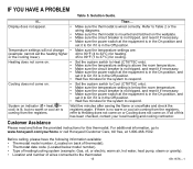
...8226; Type of heating/cooling system (example: Gas, oil, or electric; or the cooling lower). 45 to 99°F (7 to Cool (CT8775C only). • Make sure the temperature setting is coming from the registers. warm air, hot water, heat pump, steam or gravity). •...warm or cool air coming from the registers, refer to respond. For additional information, go to www.honeywell.com/yourhome or call Honeywell Customer Care, toll free, at the equipment is wired correctly. IF YOU HAVE A PROBLEM Table 5. Before calling, please have the following information available: ...
...8226; Type of heating/cooling system (example: Gas, oil, or electric; or the cooling lower). 45 to 99°F (7 to Cool (CT8775C only). • Make sure the temperature setting is coming from the registers. warm air, hot water, heat pump, steam or gravity). •...warm or cool air coming from the registers, refer to respond. For additional information, go to www.honeywell.com/yourhome or call Honeywell Customer Care, toll free, at the equipment is wired correctly. IF YOU HAVE A PROBLEM Table 5. Before calling, please have the following information available: ...
Owner's Manual
Page 16
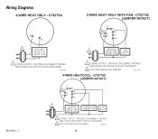
Wiring Diagrams R W 1 HEATING RELAY OR VALVE COIL 1 POWER SUPPLY. M19451 69-1676-1 O B 2 Rc G R Y W 1 HEATING COMPRESSOR FAN RELAY OR VALVE COIL CONTACTOR RELAY 1 POWER SUPPLY. PROVIDE DISCONNECT MEANS AND OVERLOAD PROTECTION AS REQUIRED. 2 FACTORY INSTALLED JUMPER. M19450 O B Rc 2 G R Y W 1 HEATING RELAY OR VALVE COIL FAN RELAY 1 POWER SUPPLY. M19452 16 PROVIDE DISCONNECT MEANS AND OVERLOAD PROTECTION AS REQUIRED. 2 FACTORY INSTALLED JUMPER. PROVIDE DISCONNECT MEANS AND OVERLOAD PROTECTION AS REQUIRED.
Wiring Diagrams R W 1 HEATING RELAY OR VALVE COIL 1 POWER SUPPLY. M19451 69-1676-1 O B 2 Rc G R Y W 1 HEATING COMPRESSOR FAN RELAY OR VALVE COIL CONTACTOR RELAY 1 POWER SUPPLY. PROVIDE DISCONNECT MEANS AND OVERLOAD PROTECTION AS REQUIRED. 2 FACTORY INSTALLED JUMPER. M19450 O B Rc 2 G R Y W 1 HEATING RELAY OR VALVE COIL FAN RELAY 1 POWER SUPPLY. M19452 16 PROVIDE DISCONNECT MEANS AND OVERLOAD PROTECTION AS REQUIRED. 2 FACTORY INSTALLED JUMPER. PROVIDE DISCONNECT MEANS AND OVERLOAD PROTECTION AS REQUIRED.
Owner's Manual
Page 17
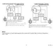
... complies with Canadian Radio Interference Regulations, CRC c. 1374. 17 69-1676-1 PROVIDE DISCONNECT MEANS AND OVERLOAD PROTECTION AS REQUIRED. 2 FACTORY INSTALLED JUMPER. M19453 3 USE A JUMPER WIRE (NOT SUPPLIED) TO CONNECT W TO Y. 4 USE EITHER O OR B FOR HEAT PUMP CHANGEOVER.
... complies with Canadian Radio Interference Regulations, CRC c. 1374. 17 69-1676-1 PROVIDE DISCONNECT MEANS AND OVERLOAD PROTECTION AS REQUIRED. 2 FACTORY INSTALLED JUMPER. M19453 3 USE A JUMPER WIRE (NOT SUPPLIED) TO CONNECT W TO Y. 4 USE EITHER O OR B FOR HEAT PUMP CHANGEOVER.


