
Owner's Manual
Page 1
...Step 3. Label Thermostat Wires ...5 Step 5. Mount Decorator Cover Plate and Thermostat Wallplate 5 Step 7. Mount the Thermostat ...11 Step 10. Registered Trademark • Patents Pending Copyright © 2004 Honeywell International Inc. CT8775A,C THE DIGITAL ROUND™ NON-PROGRAMMABLE THERMOSTATS CT8775A Heat Only Thermostat ...;ol, por favor visite nuestro sitio de web a: www.honeywell.com/yourhome. Operating the Thermostat...13 Step 12. All Rights Reserved 69-1676-1 Special Installations...4 Step 4. Wire Wallplate Terminals...8 Step 8. Set the System and Fan Switches ...
...Step 3. Label Thermostat Wires ...5 Step 5. Mount Decorator Cover Plate and Thermostat Wallplate 5 Step 7. Mount the Thermostat ...11 Step 10. Registered Trademark • Patents Pending Copyright © 2004 Honeywell International Inc. CT8775A,C THE DIGITAL ROUND™ NON-PROGRAMMABLE THERMOSTATS CT8775A Heat Only Thermostat ...;ol, por favor visite nuestro sitio de web a: www.honeywell.com/yourhome. Operating the Thermostat...13 Step 12. All Rights Reserved 69-1676-1 Special Installations...4 Step 4. Wire Wallplate Terminals...8 Step 8. Set the System and Fan Switches ...
Owner's Manual
Page 3
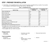
... with CT8775A Yes No Yesa Yes Yes No No No No No Compatibility with CT8775C Yes Yes Yesa Yes Yes No Yes No Yes No aCompatible with your system. or 3-wire WhiteRodgers zone valves (No. 1311 and 1361). If your system is compatible with 2-wire Honeywell zone valves.... PREPARE FOR INSTALLATION ❑ Check Table 1, the compatibility chart, to make sure the thermostat is not compatible, call Honeywell Customer Care, toll-free, 1-800-468...
... with CT8775A Yes No Yesa Yes Yes No No No No No Compatibility with CT8775C Yes Yes Yesa Yes Yes No Yes No Yes No aCompatible with your system. or 3-wire WhiteRodgers zone valves (No. 1311 and 1361). If your system is compatible with 2-wire Honeywell zone valves.... PREPARE FOR INSTALLATION ❑ Check Table 1, the compatibility chart, to make sure the thermostat is not compatible, call Honeywell Customer Care, toll-free, 1-800-468...
Owner's Manual
Page 4
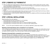
... If you are replacing a thermostat that may have either system does not work, contact your heating and cooling systems to six or more wires If you can damage the transformer. If the cover does not snap off power to the system at the furnace or the fuse/circuit ...electrical tape. Do not disconnect wires. NOTE: If none of screws, instructions, and receipt. ❑ Remove the cover from the top or bottom, check for a screw or screws that has one of these systems. For information about which thermostats will not interfere with your system, call Honeywell Customer Care, at Step ...
... If you are replacing a thermostat that may have either system does not work, contact your heating and cooling systems to six or more wires If you can damage the transformer. If the cover does not snap off power to the system at the furnace or the fuse/circuit ...electrical tape. Do not disconnect wires. NOTE: If none of screws, instructions, and receipt. ❑ Remove the cover from the top or bottom, check for a screw or screws that has one of these systems. For information about which thermostats will not interfere with your system, call Honeywell Customer Care, at Step ...
Owner's Manual
Page 5
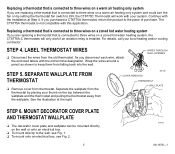
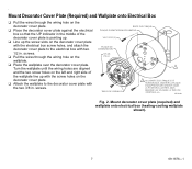
...falling back into the wall. Separate the wallplate from the thermostat by setting the thermostat fan switch to three wires on a zoned hot water heating system, the CT8775A,C thermostats will work if an isolation relay is installed. MOUNT DECORATOR COVER PLATE AND THERMOSTAT WALLPLATE ❑ ...old terminal designation. If you purchased a CT8775A thermostat, return the product to the wall, see Fig. 1. ❑ To mount onto an electrical box, see Fig. 2. 5 M19492 69-1676-1 As you are replacing a thermostat that is connected to three wires on a warm air heating only system...
...falling back into the wall. Separate the wallplate from the thermostat by setting the thermostat fan switch to three wires on a zoned hot water heating system, the CT8775A,C thermostats will work if an isolation relay is installed. MOUNT DECORATOR COVER PLATE AND THERMOSTAT WALLPLATE ❑ ...old terminal designation. If you purchased a CT8775A thermostat, return the product to the wall, see Fig. 1. ❑ To mount onto an electrical box, see Fig. 2. 5 M19492 69-1676-1 As you are replacing a thermostat that is connected to three wires on a warm air heating only system...

Owner's Manual
Page 6
...1676-1 6 Gently tap the provided anchors into the wall. ❑ If attaching the wallplate directly to the wall, pull the wires through the wiring hole on the wallplate and position it so that the UP indicator in the middle of the decorator cover plate is M19493 pointing ...up . ❑ Position the wallplate: ❑ If using the decorator cover plate, pull the wires through the wiring hole on the wallplate and place the wallplate over the screw holes. ❑ Attach the decorator cover plate (if used ) wallplate ...
...1676-1 6 Gently tap the provided anchors into the wall. ❑ If attaching the wallplate directly to the wall, pull the wires through the wiring hole on the wallplate and position it so that the UP indicator in the middle of the decorator cover plate is M19493 pointing ...up . ❑ Position the wallplate: ❑ If using the decorator cover plate, pull the wires through the wiring hole on the wallplate and place the wallplate over the screw holes. ❑ Attach the decorator cover plate (if used ) wallplate ...
Owner's Manual
Page 7
...DÉCORATIVE DANS LA POSITION ILLUSTRÉE, MAIS INSÉRER LES VIS DANS LE TROU DE MONTAGE «A». screws. ❑ Pull the wires through the wiring hole on the decorator cover plate. ❑ Place the decorator cover plate against the electrical box so that the UP indicator in the middle...with the electrical box screw holes, and attach the decorator cover plate to the decorator cover plate with two 1/2 in . Turn the wallplate until the wiring holes are aligned and the two screw holes on the left and right side of the decorator cover plate is pointing up. ❑ Line up...
...DÉCORATIVE DANS LA POSITION ILLUSTRÉE, MAIS INSÉRER LES VIS DANS LE TROU DE MONTAGE «A». screws. ❑ Pull the wires through the wiring hole on the decorator cover plate. ❑ Place the decorator cover plate against the electrical box so that the UP indicator in the middle...with the electrical box screw holes, and attach the decorator cover plate to the decorator cover plate with two 1/2 in . Turn the wallplate until the wiring holes are aligned and the two screw holes on the left and right side of the decorator cover plate is pointing up. ❑ Line up...
Owner's Manual
Page 8
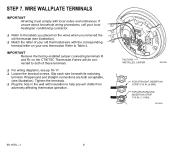
... STRAIGHT INSERTION STRIP 5/16 IN. (8 MM). Slip each wire beneath its matching terminal. Wraparound and straight connections are both of your old thermostat wire with the corresponding W terminal letter on the wires when you removed the Y old thermostat (see illustration). &#...10065; Match the letter of these terminals. ❑ For wiring diagrams, see illustration). FOR WRAPAROUND INSERTION STRIP 7/16 IN. (11 MM). If unsure about household wiring procedures, call your new thermostat. G ❑ Refer to both acceptable, (see pp...
... STRAIGHT INSERTION STRIP 5/16 IN. (8 MM). Slip each wire beneath its matching terminal. Wraparound and straight connections are both of your old thermostat wire with the corresponding W terminal letter on the wires when you removed the Y old thermostat (see illustration). &#...10065; Match the letter of these terminals. ❑ For wiring diagrams, see illustration). FOR WRAPAROUND INSERTION STRIP 7/16 IN. (11 MM). If unsure about household wiring procedures, call your new thermostat. G ❑ Refer to both acceptable, (see pp...
Owner's Manual
Page 9
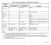
...not use . 9 69-1676-1 W - - - - Changeover in cool. (Single stage heat pump only). Call 1-800468-1502. Second stage cool. If wires will be connected to Rc. 2. Terminal Designations on the old thermostat, remove jumper between R and Rc. 3. Do not connect. Do not connect both Rh ...(see Note 1) W, W1, H Y, Y1, M G, F O B (see Note 3) C (see Note 4) X (see Note 4) B (see Note 3) W2, H2 Y2 Connect to Terminals Connect To Terminals on CT8775A on the new thermostat and connect Rh to R and R to both R and Rc on the new thermostat, remove jumper between R and Rc on CT8775C R R (see...
...not use . 9 69-1676-1 W - - - - Changeover in cool. (Single stage heat pump only). Call 1-800468-1502. Second stage cool. If wires will be connected to Rc. 2. Terminal Designations on the old thermostat, remove jumper between R and Rc. 3. Do not connect. Do not connect both Rh ...(see Note 1) W, W1, H Y, Y1, M G, F O B (see Note 3) C (see Note 4) X (see Note 4) B (see Note 3) W2, H2 Y2 Connect to Terminals Connect To Terminals on CT8775A on the new thermostat and connect Rh to R and R to both R and Rc on the new thermostat, remove jumper between R and Rc on CT8775C R R (see...
Owner's Manual
Page 15
... for heating. Wait five minutes after seeing the flame or snowflake and check the registers again. For additional information, go to www.honeywell.com/yourhome or call Honeywell Customer Care, toll free, at the equipment is in the Off position. warm air, hot water, heat pump, steam or gravity).... • Location and number of wires connected to 37°C) for this has been checked, contact your local heating and cooling contractor. ...
... for heating. Wait five minutes after seeing the flame or snowflake and check the registers again. For additional information, go to www.honeywell.com/yourhome or call Honeywell Customer Care, toll free, at the equipment is in the Off position. warm air, hot water, heat pump, steam or gravity).... • Location and number of wires connected to 37°C) for this has been checked, contact your local heating and cooling contractor. ...
Owner's Manual
Page 16
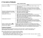
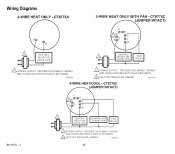
M19451 69-1676-1 O B 2 Rc G R Y W 1 HEATING COMPRESSOR FAN RELAY OR VALVE COIL CONTACTOR RELAY 1 POWER SUPPLY. PROVIDE DISCONNECT MEANS AND OVERLOAD PROTECTION AS REQUIRED. 2 FACTORY INSTALLED JUMPER. PROVIDE DISCONNECT MEANS AND OVERLOAD PROTECTION AS REQUIRED. 2 FACTORY INSTALLED JUMPER. M19452 16 M19450 O B Rc 2 G R Y W 1 HEATING RELAY OR VALVE COIL FAN RELAY 1 POWER SUPPLY. Wiring Diagrams R W 1 HEATING RELAY OR VALVE COIL 1 POWER SUPPLY. PROVIDE DISCONNECT MEANS AND OVERLOAD PROTECTION AS REQUIRED.
M19451 69-1676-1 O B 2 Rc G R Y W 1 HEATING COMPRESSOR FAN RELAY OR VALVE COIL CONTACTOR RELAY 1 POWER SUPPLY. PROVIDE DISCONNECT MEANS AND OVERLOAD PROTECTION AS REQUIRED. 2 FACTORY INSTALLED JUMPER. PROVIDE DISCONNECT MEANS AND OVERLOAD PROTECTION AS REQUIRED. 2 FACTORY INSTALLED JUMPER. M19452 16 M19450 O B Rc 2 G R Y W 1 HEATING RELAY OR VALVE COIL FAN RELAY 1 POWER SUPPLY. Wiring Diagrams R W 1 HEATING RELAY OR VALVE COIL 1 POWER SUPPLY. PROVIDE DISCONNECT MEANS AND OVERLOAD PROTECTION AS REQUIRED.
Owner's Manual
Page 17
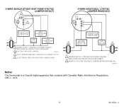
... R AND RC. M19454 Notice: This thermostat is a Class B digital apparatus that complies with Canadian Radio Interference Regulations, CRC c. 1374. 17 69-1676-1 M19453 3 USE A JUMPER WIRE (NOT SUPPLIED) TO CONNECT W TO Y. 4 USE EITHER O OR B FOR HEAT PUMP CHANGEOVER. PROVIDE DISCONNECT MEANS AND OVERLOAD PROTECTION AS REQUIRED. 2 FACTORY INSTALLED JUMPER. 4 O Rc 2 R B G Y3...
... R AND RC. M19454 Notice: This thermostat is a Class B digital apparatus that complies with Canadian Radio Interference Regulations, CRC c. 1374. 17 69-1676-1 M19453 3 USE A JUMPER WIRE (NOT SUPPLIED) TO CONNECT W TO Y. 4 USE EITHER O OR B FOR HEAT PUMP CHANGEOVER. PROVIDE DISCONNECT MEANS AND OVERLOAD PROTECTION AS REQUIRED. 2 FACTORY INSTALLED JUMPER. 4 O Rc 2 R B G Y3...


