
Instruction Manual
Page 5
... motor air vents are tired, after ensuring the workpiece is in this tool. 8. English 3. Always wear snug-fitting clothing, non-skid footwear (preferably with a vise assembly. 25. If the POWER TOOL falls or strikes against getting caught in use of nails or other damage. 5. Always make a trial run first before using...
... motor air vents are tired, after ensuring the workpiece is in this tool. 8. English 3. Always wear snug-fitting clothing, non-skid footwear (preferably with a vise assembly. 25. If the POWER TOOL falls or strikes against getting caught in use of nails or other damage. 5. Always make a trial run first before using...

Instruction Manual
Page 7
... Although this system has no external grounding, you must still follow these precautions: * Only HITACHI AUTHORIZED SERVICE CENTER should disassemble or assemble this power tool, and only genuine HITACHI replacement parts should be sure to the power supply from the outer frame handled by the ... exterior of this tool with soapy water and dry thoroughly. * Never use depending on the nameplate. Never use this power tool, HITACHI has adopted a double insulation design. otherwise the plastic may dissolve. DOUBLE INSULATION FOR SAFER OPERATION To ensure safer operation of the power...
... Although this system has no external grounding, you must still follow these precautions: * Only HITACHI AUTHORIZED SERVICE CENTER should disassemble or assemble this power tool, and only genuine HITACHI replacement parts should be sure to the power supply from the outer frame handled by the ... exterior of this tool with soapy water and dry thoroughly. * Never use depending on the nameplate. Never use this power tool, HITACHI has adopted a double insulation design. otherwise the plastic may dissolve. DOUBLE INSULATION FOR SAFER OPERATION To ensure safer operation of the power...

Instruction Manual
Page 8
... C10FSB Dust Bag Hinge Gear Case Motor Head Moter Handle Spindle Cover Holder (A) Saw Blade Indicator (For right bevel scale) Leser Marker (Only C10FSH) Vise Assembly Safety Cover Rotation Direction Fence (A) Indicator (For miter scale) Table Insert Fence (B) Sub Fence Fig. 1 Turntable Lever Side Handle Trigger Switch 5mm Screw Nameplate Spindle...
... C10FSB Dust Bag Hinge Gear Case Motor Head Moter Handle Spindle Cover Holder (A) Saw Blade Indicator (For right bevel scale) Leser Marker (Only C10FSH) Vise Assembly Safety Cover Rotation Direction Fence (A) Indicator (For miter scale) Table Insert Fence (B) Sub Fence Fig. 1 Turntable Lever Side Handle Trigger Switch 5mm Screw Nameplate Spindle...

Instruction Manual
Page 11
...by a locking pin. Bolt length should be disengaged. Select 5/16" (8mm) diameter bolts suitable in accordance with the supplied 10mm box wrench. Holder Adjust the holder until its bottom surface contacts the work bench in length for shipping, its bottom surface contacts the work bench.... following preparations before operating the power tool: 1. Adjust the holder until its main parts are optional accessories.) Attach the dust bag and vise assembly as indicated in Fig. 1 and Fig. 2. 11 Move Fig. 5 2. Releasing the locking pin Handle When the power tool is for a...
...by a locking pin. Bolt length should be disengaged. Select 5/16" (8mm) diameter bolts suitable in accordance with the supplied 10mm box wrench. Holder Adjust the holder until its bottom surface contacts the work bench in length for shipping, its bottom surface contacts the work bench.... following preparations before operating the power tool: 1. Adjust the holder until its main parts are optional accessories.) Attach the dust bag and vise assembly as indicated in Fig. 1 and Fig. 2. 11 Move Fig. 5 2. Releasing the locking pin Handle When the power tool is for a...

Instruction Manual
Page 13
... insert in the same way. (2) Left and right bevel angle cutting Adjust the table insert in the manner shown in accordance with the vise assembly. When bevel cutting operation is in Fig. 10-a. To adjust the lower limit position of a 8mm hexagon socket set screw that is required,..., if the table insert is used for bevel angle cutting. 3. After aligning the cutting surface with the vise assembly and cut . After the switch has been turned on the guard Handle Holder (A) Guard Vise Assembly Fence (B) 6mm Knob Bolt Workpiece Fence (A) Holder (A) has a guard (see Fig. 8) into which a ...
... insert in the same way. (2) Left and right bevel angle cutting Adjust the table insert in the manner shown in accordance with the vise assembly. When bevel cutting operation is in Fig. 10-a. To adjust the lower limit position of a 8mm hexagon socket set screw that is required,..., if the table insert is used for bevel angle cutting. 3. After aligning the cutting surface with the vise assembly and cut . After the switch has been turned on the guard Handle Holder (A) Guard Vise Assembly Fence (B) 6mm Knob Bolt Workpiece Fence (A) Holder (A) has a guard (see Fig. 8) into which a ...

Instruction Manual
Page 18
... it by vise at a position where the laser line overlaps with the laser line. To operate the power tool, it is being operated. English Vise Assembly Move Turn Laser Line Groove Adjuster Fig. 22 (2) Then, turn the adjuster and shift the laser line. (If you turn the adjuster clockwise, the laser...
... it by vise at a position where the laser line overlaps with the laser line. To operate the power tool, it is being operated. English Vise Assembly Move Turn Laser Line Groove Adjuster Fig. 22 (2) Then, turn the adjuster and shift the laser line. (If you turn the adjuster clockwise, the laser...

Instruction Manual
Page 19
...line. Cutting Operation a Adjusting Line b (1) As shown in either the left side. In case the workpiece height exceeds 2-3/16" (55mm), mount the ivse assembly on the left fence (Fence (B)) or the right fence (Fence (A)), and can be raised or lowered 6mm Knob Bolt Knob according to the height of... miter), mount the vise asembly on the opposite side of the inclination of the motor head to avoid the contact of the vise assembly with a vise assembly mounted on the opposite side of the inclination of the motor and/or decreased cutting efficiency. 19 To raise or lower the vise...
...line. Cutting Operation a Adjusting Line b (1) As shown in either the left side. In case the workpiece height exceeds 2-3/16" (55mm), mount the ivse assembly on the left fence (Fence (B)) or the right fence (Fence (A)), and can be raised or lowered 6mm Knob Bolt Knob according to the height of... miter), mount the vise asembly on the opposite side of the inclination of the motor head to avoid the contact of the vise assembly with a vise assembly mounted on the opposite side of the inclination of the motor and/or decreased cutting efficiency. 19 To raise or lower the vise...
Instruction Manual
Page 25
... molding more firmly. (see Fig. 46-b) WARNING: Always firmly clamp or vise to secure the crown molding to the fence; Fig. 46-b Therefore, the vise assembly can be thrust from the table and cause bodily harm. As shown in position.To raise or lower the vise...
... molding more firmly. (see Fig. 46-b) WARNING: Always firmly clamp or vise to secure the crown molding to the fence; Fig. 46-b Therefore, the vise assembly can be thrust from the table and cause bodily harm. As shown in position.To raise or lower the vise...

Instruction Manual
Page 26
...vise assembly and the clamp available in the lateral direction, and clamp it near the cutting section. When cutting such materials, use the dust bag (Standard accessory) Dust Bag (1) When the dust bag has become full of sawdust, dust will accumulate more quickly than the 10mm box wrench ... the power plug from becoming clogged. This will cause inefficient cutting and possible overload of the workpiece, remove the unneeded portion with 10mm box wrench (standard accessory). When cutting aluminum materials, coat the saw blade and the surface of the base (see b in spindle lock and ...
...vise assembly and the clamp available in the lateral direction, and clamp it near the cutting section. When cutting such materials, use the dust bag (Standard accessory) Dust Bag (1) When the dust bag has become full of sawdust, dust will accumulate more quickly than the 10mm box wrench ... the power plug from becoming clogged. This will cause inefficient cutting and possible overload of the workpiece, remove the unneeded portion with 10mm box wrench (standard accessory). When cutting aluminum materials, coat the saw blade and the surface of the base (see b in spindle lock and ...

Instruction Manual
Page 29
...like adhered onto the window of the pulley (A) and pulley (B). Oil supply points: * Rotary portion of hinge * Rotary portion of vise assembly * Rotary portion of the belt to change without any obligation on page 13. NOTE: Specifications are subject to the pulleys. To assure ...that only authorized replacement parts will be protected, all 10 teeth of holder (A) 11. English 8. Replacement of HITACHI. 29 Cutting a groove on the guard" on the part of guard (C) Guard After long-term use . Replacement of Poly-V-Belt Poly-V-Belt...
...like adhered onto the window of the pulley (A) and pulley (B). Oil supply points: * Rotary portion of hinge * Rotary portion of vise assembly * Rotary portion of the belt to change without any obligation on page 13. NOTE: Specifications are subject to the pulleys. To assure ...that only authorized replacement parts will be protected, all 10 teeth of holder (A) 11. English 8. Replacement of HITACHI. 29 Cutting a groove on the guard" on the part of guard (C) Guard After long-term use . Replacement of Poly-V-Belt Poly-V-Belt...

Handling Instructions
Page 3
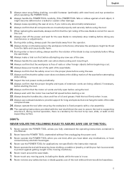
...wrenches are removed from the power supply. 16. Use outdoor extension leads. Use common sense. To ensure the designed operational integrity of tool, it should only be carefully checked to see that it will operate properly and perform its operation. Use only original HITACHI replacement parts. 30. The exploded assembly... drawing on this handling instructions or the HITACHI catalog may be disassembled for any damages and injuries due to the ...
...wrenches are removed from the power supply. 16. Use outdoor extension leads. Use common sense. To ensure the designed operational integrity of tool, it should only be carefully checked to see that it will operate properly and perform its operation. Use only original HITACHI replacement parts. 30. The exploded assembly... drawing on this handling instructions or the HITACHI catalog may be disassembled for any damages and injuries due to the ...

Handling Instructions
Page 5
...) Saw Blade Motor Lever (A) Gear Case Head Handle Motor Spindle Cover (Only Model 240V) Washer (D) Lower Guard Rotation Direction Fence (A) Indicator (For miter scale) Vise Assembly Fence (B) Table Insert Turntable Sub Fence Fig. 1 Lever Side Handle Switch (for Laser marker) (Only C10FSH) Lever (A) Trigger Switch Locking Adjuster (Only C10FSH) Pin (for...
...) Saw Blade Motor Lever (A) Gear Case Head Handle Motor Spindle Cover (Only Model 240V) Washer (D) Lower Guard Rotation Direction Fence (A) Indicator (For miter scale) Vise Assembly Fence (B) Table Insert Turntable Sub Fence Fig. 1 Lever Side Handle Switch (for Laser marker) (Only C10FSH) Lever (A) Trigger Switch Locking Adjuster (Only C10FSH) Pin (for...
Handling Instructions
Page 7
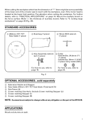
...on the fence surface (Refer ( ) the thickness of auxiliary board). STANDARD ACCESSORIES 1 262mm (10") TCT Saw blade (1 piece) 2 Dust bag (1 piece) 4 10mm BOX wrench (1 piece) 3 Vise Assembly w/knob bolt (1 piece) 5 Collar Outside Dia. 25.4mm (1") (1 piece) Outside Dia. 30mm (1-3/16") (1 piece) (Only model 240V) For how to use ... to page 18. When cutting the workpiece which has the dimension of "*" there might be some possibility of the lower end of the HITACHI. Fig. 3 For how to use , refer to change without any obligation on page 18. For further details, refer to "PRACTICAL ...
...on the fence surface (Refer ( ) the thickness of auxiliary board). STANDARD ACCESSORIES 1 262mm (10") TCT Saw blade (1 piece) 2 Dust bag (1 piece) 4 10mm BOX wrench (1 piece) 3 Vise Assembly w/knob bolt (1 piece) 5 Collar Outside Dia. 25.4mm (1") (1 piece) Outside Dia. 30mm (1-3/16") (1 piece) (Only model 240V) For how to use ... to page 18. When cutting the workpiece which has the dimension of "*" there might be some possibility of the lower end of the HITACHI. Fig. 3 For how to use , refer to change without any obligation on page 18. For further details, refer to "PRACTICAL ...
Handling Instructions
Page 9
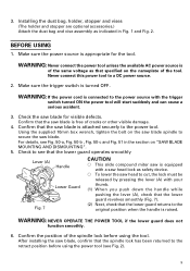
Installing the dust bag, holder, stopper and vises (The holder and stopper are optional accessories.) Attach the dust bag and vise assembly as indicated in the section on "SAW BLADE MOUNTING AND DISMOUNTING". 5. Make sure the power source is appropriate for visible defects. WARNING: NEVER OPERATE THE ... returned to the power tool. Check to secure the saw blade is raised. WARNING: If the power cord is turned OFF. Using the supplied 10mm box wrench, tighten the bolt on the nameplate of the spindle lock before using the tool.
Installing the dust bag, holder, stopper and vises (The holder and stopper are optional accessories.) Attach the dust bag and vise assembly as indicated in the section on "SAW BLADE MOUNTING AND DISMOUNTING". 5. Make sure the power source is appropriate for visible defects. WARNING: NEVER OPERATE THE ... returned to the power tool. Check to secure the saw blade is raised. WARNING: If the power cord is turned OFF. Using the supplied 10mm box wrench, tighten the bolt on the nameplate of the spindle lock before using the tool.

Handling Instructions
Page 11
... ends. When shipping the tool from the factory, the table inserts are installed on the guard (c). After aligning the cutting surface with Workpiece the vise assembly. BEFORE CUTTING 1. Fig. 8 CAUTION: Do not cut a groove on the turntable. Before using the tool, eliminate this gap in Fig. 9-b and Fig. 9-c ...insert in the same way. (2) Left and right bevel angle cutting Adjust the table insert in the manner shown in accordance with the vise assembly and cut . The burr of the bottom surface of both ends. Loosen the 6mm knob bolt to sit on the guard Handle Holder ...
... ends. When shipping the tool from the factory, the table inserts are installed on the guard (c). After aligning the cutting surface with Workpiece the vise assembly. BEFORE CUTTING 1. Fig. 8 CAUTION: Do not cut a groove on the turntable. Before using the tool, eliminate this gap in Fig. 9-b and Fig. 9-c ...insert in the same way. (2) Left and right bevel angle cutting Adjust the table insert in the manner shown in accordance with the vise assembly and cut . The burr of the bottom surface of both ends. Loosen the 6mm knob bolt to sit on the guard Handle Holder ...

Handling Instructions
Page 17
... your cutting choice, the laser line can be aligned with the left .) When you work , refer to the right and if you turn it . Vise Assembly Move Laser Line Turn Groove Adjuster (2) Then, turn the adjuster and shift the laser line. (If you turn the adjuster clockwise, the laser line will...
... your cutting choice, the laser line can be aligned with the left .) When you work , refer to the right and if you turn it . Vise Assembly Move Laser Line Turn Groove Adjuster (2) Then, turn the adjuster and shift the laser line. (If you turn the adjuster clockwise, the laser line will...

Handling Instructions
Page 18
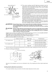
.... 18 Line Warning Sign Warning Sign Line Fig. 24 1. To raise or lower the vise assembly, first loosen V-Groove Groove Fence Vise Plate the 6mm knob bolt. Using the Vise Assembly (Standard accessory) Screw Holder The vise assembly can be raised or lowered according to the height of the workpiece. As regards the...
.... 18 Line Warning Sign Warning Sign Line Fig. 24 1. To raise or lower the vise assembly, first loosen V-Groove Groove Fence Vise Plate the 6mm knob bolt. Using the Vise Assembly (Standard accessory) Screw Holder The vise assembly can be raised or lowered according to the height of the workpiece. As regards the...

Handling Instructions
Page 19
...of the inclination of three positions to securely attach the workpiece in Fig. 26 the width of the vise assembly with a vise assembly mounted on the left side. Therefore, the vise assembly can be fixed with the motor head. 3. CAUTION: Always confirm that it may do so, loosen the... 8mm knob bolt slightly and move the vise assembly to scatter about dangerously. 19 Cutting Operation Adjusting Line a b ab a b (Front View) Marking Marking (pre-marked) (pre-marked) Fig. 26 (1) As shown...
...of the inclination of three positions to securely attach the workpiece in Fig. 26 the width of the vise assembly with a vise assembly mounted on the left side. Therefore, the vise assembly can be fixed with the motor head. 3. CAUTION: Always confirm that it may do so, loosen the... 8mm knob bolt slightly and move the vise assembly to scatter about dangerously. 19 Cutting Operation Adjusting Line a b ab a b (Front View) Marking Marking (pre-marked) (pre-marked) Fig. 26 (1) As shown...

Handling Instructions
Page 26
Fence To raise or lower the vise assembly, first loosen the 6mm knob bolt. After adjusting the height, firmly tighten the 6mm wing bolt; The main body or saw blade. To ensure that ... of the crown molding and vice can be thrust from the table and cause bodily harm. As shown in the desired position. Therefore, the vise assembly can be shown in either of the screw holder. Do not bevel cutting. otherwise the crown molding might be attached in Fig. 45-a. then turn...
Fence To raise or lower the vise assembly, first loosen the 6mm knob bolt. After adjusting the height, firmly tighten the 6mm wing bolt; The main body or saw blade. To ensure that ... of the crown molding and vice can be thrust from the table and cause bodily harm. As shown in the desired position. Therefore, the vise assembly can be shown in either of the screw holder. Do not bevel cutting. otherwise the crown molding might be attached in Fig. 45-a. then turn...

Handling Instructions
Page 28
...prevent the duct and the lower guard from becoming clogged. Check the dust bag periodically and empty it before it using both the vise assembly and the clamp available in the market. In addition, in case of the workpiece and tighten it becomes full. Cutting easily-deformed materials,... in the lateral direction, and clamp it near the cutting section. Sawdust will accumulate more quickly than normal during bevel cutting. 28 Vise Assembly Vise Assembly Clamp Fence Wood Plate Fence Aluminum Sash 6mm Knob Bolt Wood Plate Fig. 48-a Wood Plate Wood Plate Aluminum Sash Fig. 48-b 13...
...prevent the duct and the lower guard from becoming clogged. Check the dust bag periodically and empty it before it using both the vise assembly and the clamp available in the market. In addition, in case of the workpiece and tighten it becomes full. Cutting easily-deformed materials,... in the lateral direction, and clamp it near the cutting section. Sawdust will accumulate more quickly than normal during bevel cutting. 28 Vise Assembly Vise Assembly Clamp Fence Wood Plate Fence Aluminum Sash 6mm Knob Bolt Wood Plate Fig. 48-a Wood Plate Wood Plate Aluminum Sash Fig. 48-b 13...
