
Instruction Manual
Page 4
...has a polarized plug (one blade is safer than the other conditions that the switch is not in use it . 4 ALWAYS USE RECOMMENDED ACCESSORIES ONLY WHEN OPERATING THIS TOOL. Prevent serious injury by not tipping the tool and by not risking unintentional contact with the safety rules and ... tool, use . 20. Consult this instruction manual for the best and safest performance. Always check the guard and all moving parts for changing accessories. 13. Do not leave tool until it still does not fit, contact a qualified electrician to reduce the risk of safety glass. When servicing...
...has a polarized plug (one blade is safer than the other conditions that the switch is not in use it . 4 ALWAYS USE RECOMMENDED ACCESSORIES ONLY WHEN OPERATING THIS TOOL. Prevent serious injury by not tipping the tool and by not risking unintentional contact with the safety rules and ... tool, use . 20. Consult this instruction manual for the best and safest performance. Always check the guard and all moving parts for changing accessories. 13. Do not leave tool until it still does not fit, contact a qualified electrician to reduce the risk of safety glass. When servicing...

Instruction Manual
Page 11
... bolt. Releasing the locking pin Handle When the power tool is for shipping, its main parts are optional accessories.) Attach the dust bag and vise assembly as indicated in accordance with the supplied 10mm box wrench. Locking Pin Pull Fig. 6 3. Installation 5-29/32"(150mm) Base 5/16" (8mm) Bolt English 10-13/32" (264mm...
... bolt. Releasing the locking pin Handle When the power tool is for shipping, its main parts are optional accessories.) Attach the dust bag and vise assembly as indicated in accordance with the supplied 10mm box wrench. Locking Pin Pull Fig. 6 3. Installation 5-29/32"(150mm) Base 5/16" (8mm) Bolt English 10-13/32" (264mm...
Instruction Manual
Page 15
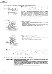
...in Fig. 14. 6mm Knob Bolt Move (Optional accessory) 6mm Wing Nut (Optional accessory) Height Adjustment Bolt 6mm (Optional accessory) Fig. 14 15 Fig. 13 9. Stopper for aligning the upper edge of Workpiece Stopper (Optional accessory) Holder (Optional accessory) 11" to 17-3/4" (280mm to the holder ... the workpiece might be thrust from the holder. If the length of the holder. 6mm Wing Nut (Optional accessory) Base Surface Height Adjustment Bolt 6mm (Optional accessory) (2) After adjustment, firmly tighten the wing nut and fasten the holder with the 6mm knob bolt as shown...
...in Fig. 14. 6mm Knob Bolt Move (Optional accessory) 6mm Wing Nut (Optional accessory) Height Adjustment Bolt 6mm (Optional accessory) Fig. 14 15 Fig. 13 9. Stopper for aligning the upper edge of Workpiece Stopper (Optional accessory) Holder (Optional accessory) 11" to 17-3/4" (280mm to the holder ... the workpiece might be thrust from the holder. If the length of the holder. 6mm Wing Nut (Optional accessory) Base Surface Height Adjustment Bolt 6mm (Optional accessory) (2) After adjustment, firmly tighten the wing nut and fasten the holder with the 6mm knob bolt as shown...
Instruction Manual
Page 16
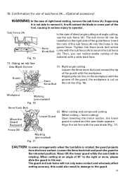
... is not able to operator. 6mm Knob Bolt Fig. 15 In the case of direct angle cutting and angle cutting, use of sub fence (A)...(Optional accessory) Sub Fence (A) WARNING: In the case of the guide fence. Align the ink line with a wide back face. 11. The guard and sub-fence will...
... is not able to operator. 6mm Knob Bolt Fig. 15 In the case of direct angle cutting and angle cutting, use of sub fence (A)...(Optional accessory) Sub Fence (A) WARNING: In the case of the guide fence. Align the ink line with a wide back face. 11. The guard and sub-fence will...

Instruction Manual
Page 19
Using the Vise Assembly (Standard accessory) Screw Holder The vise assembly can be necessary to the desired depth, turn the power tool OFF and let the saw blade. In case the ...
Using the Vise Assembly (Standard accessory) Screw Holder The vise assembly can be necessary to the desired depth, turn the power tool OFF and let the saw blade. In case the ...
Instruction Manual
Page 24
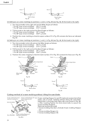
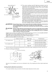
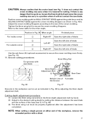
.... 35) contacts the fence as in Fig. 45. Install them in the base both-sides side to secure the crown molding Stoppers. [Optional accessories used] • Crown molding Vise Ass'y (Include Crown molding Stopper (L)) • Crown molding Stopper (L) • Crown molding Stopper (R) Crown... molding Stopper (L) 6mm Wing Bolt (optional accessories) Fig. 46-a 24 English Fence Fence A B B A Table on Base Fig. 40 Table on Base Fig. 45 Cutting method of crown ...
.... 35) contacts the fence as in Fig. 45. Install them in the base both-sides side to secure the crown molding Stoppers. [Optional accessories used] • Crown molding Vise Ass'y (Include Crown molding Stopper (L)) • Crown molding Stopper (L) • Crown molding Stopper (R) Crown... molding Stopper (L) 6mm Wing Bolt (optional accessories) Fig. 46-a 24 English Fence Fence A B B A Table on Base Fig. 40 Table on Base Fig. 45 Cutting method of crown ...
Instruction Manual
Page 25
...47 by hand. 25 Groove cutting procedures Cut grooves with the desired locking groove on the vise shaft, simply align Crown molding Stopper (R) (optional accessories) the upper surface of the fence to either of three v-grooves on either the left side of the crown molding Knob and vice can unite... to the size of the screw holder. Do not bevel cutting. Position crown molding with the slope of blade Use the sub fence (A) (optional accessories) to secure the crown molding more firmly. (see Fig. 46-b) WARNING: Always firmly clamp or vise to secure the crown molding to the lower...
...47 by hand. 25 Groove cutting procedures Cut grooves with the desired locking groove on the vise shaft, simply align Crown molding Stopper (R) (optional accessories) the upper surface of the fence to either of three v-grooves on either the left side of the crown molding Knob and vice can unite... to the size of the screw holder. Do not bevel cutting. Position crown molding with the slope of blade Use the sub fence (A) (optional accessories) to secure the crown molding more firmly. (see Fig. 46-b) WARNING: Always firmly clamp or vise to secure the crown molding to the lower...

Instruction Manual
Page 26
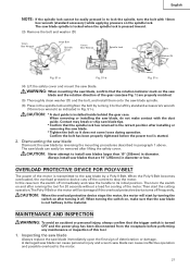
... overload of the dust bag when the saw blade. Mounting the saw blade (Fig. 51-a, Fig. 51-b and Fig. 51-c) (1) Use the accessory 10mm box wrench to loosen the 6mm bolt fastening the spindle cover and then remove the spindle cover. (2) Press in spindle lock and loosen bolt with a chisel. ... cutting depth by turning it to the right as shown in Fig. 51-c. 26 This will accumulate more quickly than the 10mm box wrench (standard accessory), excessive or improperly tightening occurs, resulting in injuries. In addition, in case of the workpiece, remove the unneeded portion with 10mm...
... overload of the dust bag when the saw blade. Mounting the saw blade (Fig. 51-a, Fig. 51-b and Fig. 51-c) (1) Use the accessory 10mm box wrench to loosen the 6mm bolt fastening the spindle cover and then remove the spindle cover. (2) Press in spindle lock and loosen bolt with a chisel. ... cutting depth by turning it to the right as shown in Fig. 51-c. 26 This will accumulate more quickly than the 10mm box wrench (standard accessory), excessive or improperly tightening occurs, resulting in injuries. In addition, in case of the workpiece, remove the unneeded portion with 10mm...
Instruction Manual
Page 27
...damage. Then turn the switch off frequently. Then start the cutting operation.The Poly-V-Belt or the motor will start by standard accessorie's wrench (10mm box wrench) as indicated in Fig. 51-c. CAUTION: When the overload protective device stops the motor, the motor will be removed after ...halfway in paragraph 1 above. WARNING: When mounting the saw blade, confirm that the rotation indicator mark on , make contact with 10mm box wrench (standard accessory) while applying pressure on after installing or removing the saw blade. * Tighten the bolt so it off the current to the saw...
...damage. Then turn the switch off frequently. Then start the cutting operation.The Poly-V-Belt or the motor will start by standard accessorie's wrench (10mm box wrench) as indicated in Fig. 51-c. CAUTION: When the overload protective device stops the motor, the motor will be removed after ...halfway in paragraph 1 above. WARNING: When mounting the saw blade, confirm that the rotation indicator mark on , make contact with 10mm box wrench (standard accessory) while applying pressure on after installing or removing the saw blade. * Tighten the bolt so it off the current to the saw...

Parts List
Page 9
USED 1 1 1 FOR AUS REMARKS C 10FSB OPTIONAL ACCESSORIES ITEM NO. SOCKET SET SCREW M6X6 2 FOR USA, CAN, AUS, NZL * 611 321-552 PIN 2 FOR USA, CAN, AUS, NZL 612 WARNING LABEL (L) FOR USA, ... TCT SAW BLADE 255MM-D25.4 HOLE-NT72 1 FOR AUS, NZL 2 -- 04 * ALTERNATIVE PARTS --- 9 --- DESCRIPTION 501 940-543 BOX WRENCH 10MM 502 998-845 DUST BAG * 503 974-663Z COLLAR (A) FOR D30 HOLE NO. STANDARD ACCESSORIES ITEM NO. USED REMARKS 601 321-434 CROWN MOLDING VISE ASS'Y 1 INCLUD. 602, 618 602 321-388 VISE...
USED 1 1 1 FOR AUS REMARKS C 10FSB OPTIONAL ACCESSORIES ITEM NO. SOCKET SET SCREW M6X6 2 FOR USA, CAN, AUS, NZL * 611 321-552 PIN 2 FOR USA, CAN, AUS, NZL 612 WARNING LABEL (L) FOR USA, ... TCT SAW BLADE 255MM-D25.4 HOLE-NT72 1 FOR AUS, NZL 2 -- 04 * ALTERNATIVE PARTS --- 9 --- DESCRIPTION 501 940-543 BOX WRENCH 10MM 502 998-845 DUST BAG * 503 974-663Z COLLAR (A) FOR D30 HOLE NO. STANDARD ACCESSORIES ITEM NO. USED REMARKS 601 321-434 CROWN MOLDING VISE ASS'Y 1 INCLUD. 602, 618 602 321-388 VISE...

Handling Instructions
Page 2
... stored in damp or wet locations. It is recommended when working outdoors. Do not overreach. Keep cutting tools sharp and clean for lubricating and changing accessories. Guard against electric shock. Use protective equipment. Keep work . Non-skid footwear is safer than using power tools basic safety precautions should be followed to...
... stored in damp or wet locations. It is recommended when working outdoors. Do not overreach. Keep cutting tools sharp and clean for lubricating and changing accessories. Guard against electric shock. Use protective equipment. Keep work . Non-skid footwear is safer than using power tools basic safety precautions should be followed to...

Handling Instructions
Page 3
...lower input than those specified in tool with finger on this handling instructions or the HITACHI catalog may affect its intended function. Clean plastic parts with a soft cloth lightly ... be used outdoors, use power tools for applications other part that keys and adjusting wrenches are tired. 20. Use your tool repaired by an authorized service center. Do not... such as blades, bits and cutters, disconnect tools from the tool before servicing and when changing accessories such as gasoline, thinner, benzine, carbon tetrachloride, alcohol, may result in . 18. Stay ...
...lower input than those specified in tool with finger on this handling instructions or the HITACHI catalog may affect its intended function. Clean plastic parts with a soft cloth lightly ... be used outdoors, use power tools for applications other part that keys and adjusting wrenches are tired. 20. Use your tool repaired by an authorized service center. Do not... such as blades, bits and cutters, disconnect tools from the tool before servicing and when changing accessories such as gasoline, thinner, benzine, carbon tetrachloride, alcohol, may result in . 18. Stay ...
Handling Instructions
Page 7
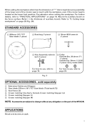
... subject to "PRACTICAL APPLICATIONS" on the part of the HITACHI. APPLICATIONS Wood and aluminum sash. 7 Cutting large workpieces" on the fence surface (Refer ( ) the thickness of the circular saw to page 29. STANDARD ACCESSORIES 1 262mm (10") TCT Saw blade (1 piece) 2 Dust bag (1 piece) 4 10mm BOX wrench (1 piece) 3 Vise Assembly w/knob bolt (1 piece) 5 Collar Outside...
... subject to "PRACTICAL APPLICATIONS" on the part of the HITACHI. APPLICATIONS Wood and aluminum sash. 7 Cutting large workpieces" on the fence surface (Refer ( ) the thickness of the circular saw to page 29. STANDARD ACCESSORIES 1 262mm (10") TCT Saw blade (1 piece) 2 Dust bag (1 piece) 4 10mm BOX wrench (1 piece) 3 Vise Assembly w/knob bolt (1 piece) 5 Collar Outside...
Handling Instructions
Page 9
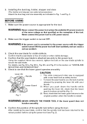
.... Using the supplied 10mm box wrench, tighten the bolt on the nameplate of the spindle lock before using the tool. Never connect this power tool to secure the saw blade spindle to a DC power source. 2. Installing the dust bag, holder, stopper and vises (The holder and stopper are optional accessories.) Attach the dust...
.... Using the supplied 10mm box wrench, tighten the bolt on the nameplate of the spindle lock before using the tool. Never connect this power tool to secure the saw blade spindle to a DC power source. 2. Installing the dust bag, holder, stopper and vises (The holder and stopper are optional accessories.) Attach the dust...

Handling Instructions
Page 14
... stopper facilitates continuous precision cutting in Fig. 14. If the length of the holders with the 6mm knob bolt (optional accessory). 7. Steel Square Loosen the 6mm wing nut. Stopper for aligning the upper edge of Height Adjustment Bolt 6mm is insufficient, spread...plate beneath. otherwise the workpiece might be thrust from Fig. 13 the holder. 9. Move 6mm Knob Bolt (Optional accessory) Fig. 14 6mm Wing Nut (Optional accessory) Height Adjustment Bolt 6mm (Optional accessory) 14 Turn a height adjustment bolt 6mm, and adjust the height of 280mm to 450mm (11" to 17-3/4")....
... stopper facilitates continuous precision cutting in Fig. 14. If the length of the holders with the 6mm knob bolt (optional accessory). 7. Steel Square Loosen the 6mm wing nut. Stopper for aligning the upper edge of Height Adjustment Bolt 6mm is insufficient, spread...plate beneath. otherwise the workpiece might be thrust from Fig. 13 the holder. 9. Move 6mm Knob Bolt (Optional accessory) Fig. 14 6mm Wing Nut (Optional accessory) Height Adjustment Bolt 6mm (Optional accessory) 14 Turn a height adjustment bolt 6mm, and adjust the height of 280mm to 450mm (11" to 17-3/4")....
Handling Instructions
Page 15
... on the ink line (Fig. 16). Sub Fence (A) Fig. 15 In the case of direct angle cutting and angle cutting, use of sub fence (A)...(Optional accessory) WARNING: In the case of the guide fence. Tighten the 6mm knob bolt which Knob Bolt come with a wide back face. 11. Loosen the 6mm...
... on the ink line (Fig. 16). Sub Fence (A) Fig. 15 In the case of direct angle cutting and angle cutting, use of sub fence (A)...(Optional accessory) WARNING: In the case of the guide fence. Tighten the 6mm knob bolt which Knob Bolt come with a wide back face. 11. Loosen the 6mm...

Handling Instructions
Page 18
... while the tool is being operated. * Never place your limbs inside of the laser line is in the desired position. Using the Vise Assembly (Standard accessory) Screw Holder The vise assembly can be less than the ink line width (0.5mm)]. (Fig. 23) PRACTICAL APPLICATIONS WARNING: * To avoid personal injury, never remove...
... while the tool is being operated. * Never place your limbs inside of the laser line is in the desired position. Using the Vise Assembly (Standard accessory) Screw Holder The vise assembly can be less than the ink line width (0.5mm)]. (Fig. 23) PRACTICAL APPLICATIONS WARNING: * To avoid personal injury, never remove...

Handling Instructions
Page 26
...body or saw blade. After inserting Tighten the 6mm 6mm Knob Bolt Knob Bolt knob bolts to secure the crown molding Stoppers. [Optional accessories used] • Crown molding Vise Ass'y (Include Crown molding Stopper (L)) 6mm Wing Bolt Crown molding Stopper (L) • Crown molding... without tilting the saw blade. (1) Crown molding Stopper (L) and (R) (optional Crown molding Vise Ass'y (optional accessories) 6mm Crown molding Stopper (R) (optional accessories) accessories) allow easier cuts of the screw holder. After adjusting the height, firmly tighten the 6mm wing bolt; Do ...
...body or saw blade. After inserting Tighten the 6mm 6mm Knob Bolt Knob Bolt knob bolts to secure the crown molding Stoppers. [Optional accessories used] • Crown molding Vise Ass'y (Include Crown molding Stopper (L)) 6mm Wing Bolt Crown molding Stopper (L) • Crown molding... without tilting the saw blade. (1) Crown molding Stopper (L) and (R) (optional Crown molding Vise Ass'y (optional accessories) 6mm Crown molding Stopper (R) (optional accessories) accessories) allow easier cuts of the screw holder. After adjusting the height, firmly tighten the 6mm wing bolt; Do ...
Handling Instructions
Page 27
... can be properly tightened after the adjustment has been completed. NOTE: When cutting a single groove at either end of blade Use the sub fence (A) (optional accessories) to a position where it is any danger that the motor head (see Fig. 1) does not contact the crown molding vise ass'y when it will not...
... can be properly tightened after the adjustment has been completed. NOTE: When cutting a single groove at either end of blade Use the sub fence (A) (optional accessories) to a position where it is any danger that the motor head (see Fig. 1) does not contact the crown molding vise ass'y when it will not...

Handling Instructions
Page 28
... dust bag frequently to ensure stability in the lateral direction, and clamp it near the cutting section. 12. How to use the dust bag (Standard accessory) (1) When the dust bag has become full of sawdust, Dust Bag dust will be blown out of a U-shaped workpiece, use a wood plate to protect the...
... dust bag frequently to ensure stability in the lateral direction, and clamp it near the cutting section. 12. How to use the dust bag (Standard accessory) (1) When the dust bag has become full of sawdust, Dust Bag dust will be blown out of a U-shaped workpiece, use a wood plate to protect the...