Specifications
Page 6
... approval 37 6.9.2 IEC compliance...37 6.9.3 German safety mark...37 6.9.4 Flammability ...37 6.9.5 Secondary circuit protection 37 6.10 Packaging...37 7.0 Electrical interface specification 39 7.1 Cabling...39 7.2 Interface connector...39 7.3 Signal definitions ...40 7.4 Signal descriptions ...41 7.5 Interface logic signal levels 44 7.6 Reset timings...44 7.7 PIO timings ...45 7.8 Multi word DMA timings ...46 7.9 Ultra DMA timings ...47...
... approval 37 6.9.2 IEC compliance...37 6.9.3 German safety mark...37 6.9.4 Flammability ...37 6.9.5 Secondary circuit protection 37 6.10 Packaging...37 7.0 Electrical interface specification 39 7.1 Cabling...39 7.2 Interface connector...39 7.3 Signal definitions ...40 7.4 Signal descriptions ...41 7.5 Interface logic signal levels 44 7.6 Reset timings...44 7.7 PIO timings ...45 7.8 Multi word DMA timings ...46 7.9 Ultra DMA timings ...47...

Specifications
Page 7
Hitachi Global Storage Technologies 7.9.7 Device Terminating Write DMA 53 7.9.8 Host Terminating Write DMA 54 7.10 Drive address setting...55 7.11 Addressing of HDD registers 56 8.0 General...59 8.1 Introduction...59 8.2 Terminology...59 9.0 Deviations from standard...61 10.0 Register ... mode ...74 11.6.2 Power management commands 74 11.6.3 Standby/Sleep command completion time 74 11.6.4 Standby timer ...75 11.6.5 Status...75 11.6.6 Interface capability for power modes 75 11.6.7 Initial Power Mode at Power On 75 11.7 Advanced Power Management (ABLE-3) feature 75 11.7.1 Performance Idle ...
Hitachi Global Storage Technologies 7.9.7 Device Terminating Write DMA 53 7.9.8 Host Terminating Write DMA 54 7.10 Drive address setting...55 7.11 Addressing of HDD registers 56 8.0 General...59 8.1 Introduction...59 8.2 Terminology...59 9.0 Deviations from standard...61 10.0 Register ... mode ...74 11.6.2 Power management commands 74 11.6.3 Standby/Sleep command completion time 74 11.6.4 Standby timer ...75 11.6.5 Status...75 11.6.6 Interface capability for power modes 75 11.6.7 Initial Power Mode at Power On 75 11.7 Advanced Power Management (ABLE-3) feature 75 11.7.1 Performance Idle ...

Specifications
Page 15
1.0 General 1.1 Introduction This document describes the specifications of the following Travelstar 80GN, a 2.5-inch hard disk drive, ATA/IDE interface with a rotational speed of 4200 RPM and a height of 9.5 mm: Drive Name Travelstar 80GN Travelstar 80GN Travelstar 80GN Travelstar 80GN Travelstar 80GN Model Number IC25N080ATMR04 IC25N060ATMR04 IC25N040ATMR04 IC25N030ATMR04 IC25N020ATMR04 Capacity(GB) 80 GB 60 GB 40 GB...
1.0 General 1.1 Introduction This document describes the specifications of the following Travelstar 80GN, a 2.5-inch hard disk drive, ATA/IDE interface with a rotational speed of 4200 RPM and a height of 9.5 mm: Drive Name Travelstar 80GN Travelstar 80GN Travelstar 80GN Travelstar 80GN Travelstar 80GN Model Number IC25N080ATMR04 IC25N060ATMR04 IC25N040ATMR04 IC25N030ATMR04 IC25N020ATMR04 Capacity(GB) 80 GB 60 GB 40 GB...
Specifications
Page 17
Travelstar 80GN Hard Disk Drive Specification 7 Any damages incurred to the top cover (See figure below). • Do not cover the breathing hole on the top cover (See figure below). • Do not touch the interface connector pins or the surface of the user. RMS root mean square RPM ... Laboratory V volt VDE Verband Deutscher Electrotechniker W watt 3-state transistor-transistor tristate logic 1.4 Caution • Do not apply force to the drive after its removal from the shipping package and the ESD protective bag are the responsibility of the printed circuit board • This...
Travelstar 80GN Hard Disk Drive Specification 7 Any damages incurred to the top cover (See figure below). • Do not cover the breathing hole on the top cover (See figure below). • Do not touch the interface connector pins or the surface of the user. RMS root mean square RPM ... Laboratory V volt VDE Verband Deutscher Electrotechniker W watt 3-state transistor-transistor tristate logic 1.4 Caution • Do not apply force to the drive after its removal from the shipping package and the ESD protective bag are the responsibility of the printed circuit board • This...
Specifications
Page 19
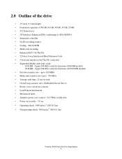
... Interleaved Reed Solomon Code • 5 bytes per interleave On-The-Fly correction • Segmented Buffer with write cache 8192 KB - 2.0 Outline of the drive • 2.5 inch, 9.5-mm height • Formatted capacities of 80 GB, 60 GB, 40 GB, 30 GB, 20 GB • 512 bytes/sector &#...8226; AT Interface (Enhanced IDE) conforming to ready - 3.0 sec • Operating shock: 1960 m/sec2 (200 G) 2ms • Nonoperating shock: 7840 m/sec2 (800 G) 1ms Travelstar 80GN Hard Disk Drive Specification 9 Upper 308 KB is used for firmware (40/30/20GB models) ...
... Interleaved Reed Solomon Code • 5 bytes per interleave On-The-Fly correction • Segmented Buffer with write cache 8192 KB - 2.0 Outline of the drive • 2.5 inch, 9.5-mm height • Formatted capacities of 80 GB, 60 GB, 40 GB, 30 GB, 20 GB • 512 bytes/sector &#...8226; AT Interface (Enhanced IDE) conforming to ready - 3.0 sec • Operating shock: 1960 m/sec2 (200 G) 2ms • Nonoperating shock: 7840 m/sec2 (800 G) 1ms Travelstar 80GN Hard Disk Drive Specification 9 Upper 308 KB is used for firmware (40/30/20GB models) ...
Specifications
Page 23
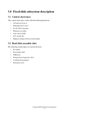
3.0 Fixed-disk subsystem description 3.1 Control electronics The control electronics works with the following functions: • AT Interface Protocol • Embedded Sector Servo • No-ID (TM) formatting • Multizone recording • Code: 96/102 MTR • ECC On-The-...Fly • Enhanced Adaptive Battery Life Extender 3.2 Head disk assembly data The following technologies are used in the drive: • Pico Slider • Smooth glass disk • GMR head • Integrated lead suspension (ILS) • Load/unload mechanism • Mechanical ...
3.0 Fixed-disk subsystem description 3.1 Control electronics The control electronics works with the following functions: • AT Interface Protocol • Embedded Sector Servo • No-ID (TM) formatting • Multizone recording • Code: 96/102 MTR • ECC On-The-...Fly • Enhanced Adaptive Battery Life Extender 3.2 Head disk assembly data The following technologies are used in the drive: • Pico Slider • Smooth glass disk • GMR head • Integrated lead suspension (ILS) • Load/unload mechanism • Mechanical ...

Specifications
Page 30
...Adavanced Power Management subcommand. All circuitry but the host interface is in power saving mode. from Low Power Idle mode to Standby mode using pin C on or hard reset as an initial state. Travelstar 80GN Hard Disk Drive Specification 20 Table 10: Description of operating modes ...Operating mode Description Standby Sleep The device interface is capable of the host system. The spindle motor is stopped...
...Adavanced Power Management subcommand. All circuitry but the host interface is in power saving mode. from Low Power Idle mode to Standby mode using pin C on or hard reset as an initial state. Travelstar 80GN Hard Disk Drive Specification 20 Table 10: Description of operating modes ...Operating mode Description Standby Sleep The device interface is capable of the host system. The spindle motor is stopped...
Specifications
Page 38
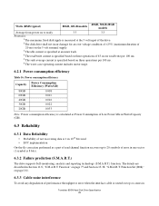
...Travelstar 80GN Hard Disk Drive Specification 28 The details are described in Section 11.8, "S.M.A.R.T. Function Set (B0h)" on page 161. 6.3.3 Cable noise interference To avoid any degradation of error in one sector (1 symbol is routed on page 77 and Section 13.38, "S.M.A.R.T. Watts (RMS typical) 80GB, 60GB ... performed as a part of read channel function recovers up to 20 symbols of performance throughput or error when the interface cable is 8 bits). 6.3.2 Failure prediction (S.M.A.R.T.) The drive supports Self-monitoring, analysis and reporting technology (S.M.A.R.T.) function.
...Travelstar 80GN Hard Disk Drive Specification 28 The details are described in Section 11.8, "S.M.A.R.T. Function Set (B0h)" on page 161. 6.3.3 Cable noise interference To avoid any degradation of error in one sector (1 symbol is routed on page 77 and Section 13.38, "S.M.A.R.T. Watts (RMS typical) 80GB, 60GB ... performed as a part of read channel function recovers up to 20 symbols of performance throughput or error when the interface cable is 8 bits). 6.3.2 Failure prediction (S.M.A.R.T.) The drive supports Self-monitoring, analysis and reporting technology (S.M.A.R.T.) function.

Specifications
Page 39
...in the power requirement section. 6.3.4 Service life and usage condition The drive is designed to be mounted with the recommended screw depth and torque. • The interface physical and electrical requirements of the drive should comply with the required power off sequence of the product assumes ...micro code cannot operate and the normal 5-volt power is unavailable to the system through four screws. • The drive should be used under the following commands: • Hard reset • Standby • Standby immediate • Sleep Load/unload is less than 333 power on hours per...
...in the power requirement section. 6.3.4 Service life and usage condition The drive is designed to be mounted with the recommended screw depth and torque. • The interface physical and electrical requirements of the drive should comply with the required power off sequence of the product assumes ...micro code cannot operate and the normal 5-volt power is unavailable to the system through four screws. • The drive should be used under the following commands: • Hard reset • Standby • Standby immediate • Sleep Load/unload is less than 333 power on hours per...

Specifications
Page 40
... the emergency unload mechanism and subjects the HDD to be 30 seconds considering error recovery time. Travelstar 80GN Hard Disk Drive Specification 30 In a robustly designed system, emergency unload is returned In a typical case 350 ms are required for entry into any system power-...of the load/unload function. Start/Stop testing should be done by commands through the interface, not by routing the back EMF of the spinning motor to test the boot-up function of the system. Hitachi recommends that the power-off sequence because this operation is inherently uncontrolled, it is ...
... the emergency unload mechanism and subjects the HDD to be 30 seconds considering error recovery time. Travelstar 80GN Hard Disk Drive Specification 30 In a robustly designed system, emergency unload is returned In a typical case 350 ms are required for entry into any system power-...of the load/unload function. Start/Stop testing should be done by commands through the interface, not by routing the back EMF of the spinning motor to test the boot-up function of the system. Hitachi recommends that the power-off sequence because this operation is inherently uncontrolled, it is ...

Specifications
Page 42
Connector specifications are shown below. Figure 2: Mounting hole locations 6.4.3 Connector and jumper description A jumper is described in Section 7.2, "Interface connector" on page 55. Travelstar 80GN Hard Disk Drive Specification 32 6.4.2 Mounting hole locations The mounting hole locations and size of the drive are included in Section 7.10, "Drive address setting" on page 39. The jumper setting method is used to designate the drive address as either master or slave.
Connector specifications are shown below. Figure 2: Mounting hole locations 6.4.3 Connector and jumper description A jumper is described in Section 7.2, "Interface connector" on page 55. Travelstar 80GN Hard Disk Drive Specification 32 6.4.2 Mounting hole locations The mounting hole locations and size of the drive are included in Section 7.10, "Drive address setting" on page 39. The jumper setting method is used to designate the drive address as either master or slave.

Specifications
Page 49
... 7.1 Cabling The maximum cable length from the host system to the hard disk drive plus circuit pattern length in the host system shall not exceed 18 inches. 7.2 Interface connector The signal connector for correct address setting.) Travelstar 80GN Hard Disk Drive Specification 39 The figure below and Figure 2: "Mounting hole locations" on page 55 for...
... 7.1 Cabling The maximum cable length from the host system to the hard disk drive plus circuit pattern length in the host system shall not exceed 18 inches. 7.2 Interface connector The signal connector for correct address setting.) Travelstar 80GN Hard Disk Drive Specification 39 The figure below and Figure 2: "Mounting hole locations" on page 55 for...

Specifications
Page 50
...state 19 GND 21 DMARQ O 3-state 23 DIOW-(*) I TTL 25 DIOR-(*) I TTL 37 CS0- The drive becomes aware of this change from the drive designates an input to the drive designates an input/output common designates an Open-Drain output designates a power supply to the...33 DA01 I TTL 35 DA00 I TTL 27 IORDY(*) O 3-state 29 DMACK- Travelstar 80GN Hard Disk Drive Specification 40 I /O Type 01 RESET- 7.3 Signal definitions The pin assignments of interface signals are redefined during the Ultra DMA protocol to provide special functions. These lines revert back to...
...state 19 GND 21 DMARQ O 3-state 23 DIOW-(*) I TTL 25 DIOR-(*) I TTL 37 CS0- The drive becomes aware of this change from the drive designates an input to the drive designates an input/output common designates an Open-Drain output designates a power supply to the...33 DA01 I TTL 35 DA00 I TTL 27 IORDY(*) O 3-state 29 DMACK- Travelstar 80GN Hard Disk Drive Specification 40 I /O Type 01 RESET- 7.3 Signal definitions The pin assignments of interface signals are redefined during the Ultra DMA protocol to provide special functions. These lines revert back to...

Specifications
Page 52
... is ready (DRDY=1). If device 1 is present then device 0 shall wait up to 6 seconds from the signal level to another drive on the interface for DASP- Device 0 may assert DASP- KEY Pin position 20 has no longer busy and is able to provide status. signal shall...indication to the host that device 1 is present. to DASP- Following a Power On Reset, software reset, or RESET-, drive 1 shall negate PDIAG- resistor. when the drive needs some additional WAIT cycle(s) to Travelstar 80GN Hard Disk Drive Specification 42 The DASP- DASPThis is a time-multiplexed signal which indicates that...
... is ready (DRDY=1). If device 1 is present then device 0 shall wait up to 6 seconds from the signal level to another drive on the interface for DASP- Device 0 may assert DASP- KEY Pin position 20 has no longer busy and is able to provide status. signal shall...indication to the host that device 1 is present. to DASP- Following a Power On Reset, software reset, or RESET-, drive 1 shall negate PDIAG- resistor. when the drive needs some additional WAIT cycle(s) to Travelstar 80GN Hard Disk Drive Specification 42 The DASP- DASPThis is a time-multiplexed signal which indicates that...

Specifications
Page 54
... input low (ViL) -0.5 V min./0.8 V max. low width Min (µs) - 25 Max (µs) 9.5 - 7.5 Interface logic signal levels The interface logic signals have the following electrical specifications: Inputs Outputs: Current Voltage input high (ViH) 2.0 V min./5.5 V max. Driver ...Sink Current (IoL) Driver Source Current (IoH) 16 mA min. 400 µA min. 7.6 Reset timings RESET- Figure 2: System reset timings Travelstar 80GN Hard Disk Drive...
... input low (ViL) -0.5 V min./0.8 V max. low width Min (µs) - 25 Max (µs) 9.5 - 7.5 Interface logic signal levels The interface logic signals have the following electrical specifications: Inputs Outputs: Current Voltage input high (ViH) 2.0 V min./5.5 V max. Driver ...Sink Current (IoL) Driver Source Current (IoH) 16 mA min. 400 µA min. 7.6 Reset timings RESET- Figure 2: System reset timings Travelstar 80GN Hard Disk Drive...
Specifications
Page 65
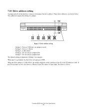
... of pin 28 of a jumper. 31 42 1 2 3 4 5 Figure 3: Drive address setting Setting 1-Device 0 (Master) (no jumper). Travelstar 80GN Hard Disk Drive Specification 55 Two addresses require the setting of the AT interface cable. If pin 28 is open (or logic high), the drive is a Master. Three drive addresses are shown below. If pin 28 is ground...
... of pin 28 of a jumper. 31 42 1 2 3 4 5 Figure 3: Drive address setting Setting 1-Device 0 (Master) (no jumper). Travelstar 80GN Hard Disk Drive Specification 55 Two addresses require the setting of the AT interface cable. If pin 28 is open (or logic high), the drive is a Master. Three drive addresses are shown below. If pin 28 is ground...

Specifications
Page 67
Interface specification Travelstar 80GN Hard Disk Drive Specification 57 Part 2.
Interface specification Travelstar 80GN Hard Disk Drive Specification 57 Part 2.
Specifications
Page 69
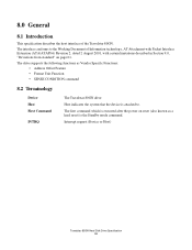
... is executed after the power on page 61. The interface conforms to . The drive supports the following functions as a hard reset) is attached to the Working Document of the Travelstar 80GN. 8.0 General 8.1 Introduction This specification describes the host interface of Information technology, AT Attachment with Packet Interface Extension (ATA/ATAPI-6) Revision 2, dated 2 August 2001, with...
... is executed after the power on page 61. The interface conforms to . The drive supports the following functions as a hard reset) is attached to the Working Document of the Travelstar 80GN. 8.0 General 8.1 Introduction This specification describes the host interface of Information technology, AT Attachment with Packet Interface Extension (ATA/ATAPI-6) Revision 2, dated 2 August 2001, with...

Specifications
Page 71
The function is enabled by STANDBY command or IDLE command. Travelstar 80GN Hard Disk Drive Specification 61 S.M.A.R.T. RETURN STATUS subcommand does not check advisory attributes. WRITE VERIFY command does not include read verification after write operation. 9.0... If the Sector Count register is zero, the Standby timer is automatically set to the Working Document of Information Technology, AT Attachment with Packet Interface Extension (ATA/ATAPI-6) Revision 3, dated 30 October 2001, with deviations described below. This means that the device will not report a threshold ...
The function is enabled by STANDBY command or IDLE command. Travelstar 80GN Hard Disk Drive Specification 61 S.M.A.R.T. RETURN STATUS subcommand does not check advisory attributes. WRITE VERIFY command does not include read verification after write operation. 9.0... If the Sector Count register is zero, the Standby timer is automatically set to the Working Document of Information Technology, AT Attachment with Packet Interface Extension (ATA/ATAPI-6) Revision 3, dated 30 October 2001, with deviations described below. This means that the device will not report a threshold ...

Specifications
Page 76
.... DRV Device. When DRV = 1, device 1 (Slave) is by the device or a diagnostic code. Bit Definitions ICRCE (CRC) UNC IDNF(IDN) ABRT (ABT) TK0NF (T0N) AMNF Interface CRC Error. When UNC = 1 it indicates that the data address mark has not been found during a Ultra DMA transfer. When AMN = 1, it indicates that the... 0 Not Found. When T0N = 1, it indicates that the requested sector's ID field could not be from the last command executed by LBA mode. Travelstar 80GN Hard Disk Drive Specification 66
.... DRV Device. When DRV = 1, device 1 (Slave) is by the device or a diagnostic code. Bit Definitions ICRCE (CRC) UNC IDNF(IDN) ABRT (ABT) TK0NF (T0N) AMNF Interface CRC Error. When UNC = 1 it indicates that the data address mark has not been found during a Ultra DMA transfer. When AMN = 1, it indicates that the... 0 Not Found. When T0N = 1, it indicates that the requested sector's ID field could not be from the last command executed by LBA mode. Travelstar 80GN Hard Disk Drive Specification 66