Specifications
Page 7
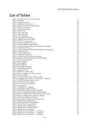
... 86 Table 52 Format Unit Command (F7h) 87 Table 53 Identify Device Command (ECh) 88 Table 54 Identify device information 89 Table 55 Identify device information --- Single track seek time 20 Table 8. Drive ready time 22 Table 12. Swept sine vibration 35 Table 19. Continued...90 Table 56 Identify device information --- Random vibration PSD profile breakpoints (operating) 35 Table 18. Formatted capacity by ATA commands 52 Table 34 Power conditions 54 Table 35 Command table for device lock operation 62 Table 36 Command table for device lock operation - Magnetic...
... 86 Table 52 Format Unit Command (F7h) 87 Table 53 Identify Device Command (ECh) 88 Table 54 Identify device information 89 Table 55 Identify device information --- Single track seek time 20 Table 8. Drive ready time 22 Table 12. Swept sine vibration 35 Table 19. Continued...90 Table 56 Identify device information --- Random vibration PSD profile breakpoints (operating) 35 Table 18. Formatted capacity by ATA commands 52 Table 34 Power conditions 54 Table 35 Command table for device lock operation 62 Table 36 Command table for device lock operation - Magnetic...

Specifications
Page 41
...mate Differential signal B from Phy S3 A- If pin P11 is not connected in the host (floating), the drive shall enable staggered spin-up . The following standard shall be used. Serial ATA International Organization: Serial ATA Revision 2.6 15-February -2007 41/173 Interface connector pins and I/O signals Signal Gnd RX+ RXGnd TXTX+ Gnd... 5V power,pre-charge,2nd Mate P8 V5 5V power Power P9 V5 P10 Gnd 5V power 2nd mate P11 DAS/DSS P12 Gnd Device Activity Signal / Disable Staggered Spinup1 1st mate P13 V12 12V power,pre-chage,2nd mate P14 V12 12V power P15 V12 12V power...
...mate Differential signal B from Phy S3 A- If pin P11 is not connected in the host (floating), the drive shall enable staggered spin-up . The following standard shall be used. Serial ATA International Organization: Serial ATA Revision 2.6 15-February -2007 41/173 Interface connector pins and I/O signals Signal Gnd RX+ RXGnd TXTX+ Gnd... 5V power,pre-charge,2nd Mate P8 V5 5V power Power P9 V5 P10 Gnd 5V power 2nd mate P11 DAS/DSS P12 Gnd Device Activity Signal / Disable Staggered Spinup1 1st mate P13 V12 12V power,pre-chage,2nd mate P14 V12 12V power P15 V12 12V power...

Specifications
Page 44
Interrupt request (Device or Host) 44/173 ATA/ATAPI Command Set (ATA8-ACS) Revision 3f dated on 11 December 2006 HTS7220XXK9SA00 / HTS7220XXK9A300 support following functions as Vendor Specific Function. • Format Unit Function • SENSE CONDITION command 8.2 Device Host INTRQ Terminology Device indicates HTS7220XXK9SA00 / HTS7220XXK9A300 Host indicates the system that the device is attached to following...
Interrupt request (Device or Host) 44/173 ATA/ATAPI Command Set (ATA8-ACS) Revision 3f dated on 11 December 2006 HTS7220XXK9SA00 / HTS7220XXK9A300 support following functions as Vendor Specific Function. • Format Unit Function • SENSE CONDITION command 8.2 Device Host INTRQ Terminology Device indicates HTS7220XXK9SA00 / HTS7220XXK9A300 Host indicates the system that the device is attached to following...

Specifications
Page 45
...part. 11 Registers In Serial ATA, the host adapter contains a set of registers that shadow the contents of the traditional device registers, referred to the device or posting status from Standard The device conforms to Sector Count Register when the device is written in the Shadow ...the new contents. • Command register is written in the Shadow Register Block • Device Control register is in negative reliability status. The interface conforms to the Serial ATA Specification. That is requested 45/173 RETURN STATUS subcommand does not check advisory attributes. This ...
...part. 11 Registers In Serial ATA, the host adapter contains a set of registers that shadow the contents of the traditional device registers, referred to the device or posting status from Standard The device conforms to Sector Count Register when the device is written in the Shadow ...the new contents. • Command register is written in the Shadow Register Block • Device Control register is in negative reliability status. The interface conforms to the Serial ATA Specification. That is requested 45/173 RETURN STATUS subcommand does not check advisory attributes. This ...

Specifications
Page 46
...=1 LBA high LBA high current LBA mid HOB=0 LBA high (exp) LBA high previous LBA mid HOB=1 Device Device Device Command Command N/A Control Device Control N/A Status N/A Status Error N/A Error Table 24 Register naming convention and correspondence 46/173 7K200 SATA OEM... Specification 11.1 Register naming convention This specification uses the same naming conventions for the Command Block Registers as the ATA8-ACS standard. Serial ATA...
...=1 LBA high LBA high current LBA mid HOB=0 LBA high (exp) LBA high previous LBA mid HOB=1 Device Device Device Command Command N/A Control Device Control N/A Status N/A Status Error N/A Error Table 24 Register naming convention and correspondence 46/173 7K200 SATA OEM... Specification 11.1 Register naming convention This specification uses the same naming conventions for the Command Block Registers as the ATA8-ACS standard. Serial ATA...

Specifications
Page 50
... in write cache has been written. (*2) Default value on POR is reset. In other mechanical parametric, and sets default values. The device resets the interface circuitry as well as Soft Reset. ECC bytes - Read look-ahead - Table 29 Reset Response Table 12.1.1 Register ...7K200 SATA OEM Specification 12 General Operation Descriptions 12.1 Reset Response There are three types of reset in ATA as follows: Power On Reset (POR) The device executes a series of registers (*2) O o o Reverting programmed parameters to default O (*6) (*3) - COMRESET COMRESET is issued in ...
... in write cache has been written. (*2) Default value on POR is reset. In other mechanical parametric, and sets default values. The device resets the interface circuitry as well as Soft Reset. ECC bytes - Read look-ahead - Table 29 Reset Response Table 12.1.1 Register ...7K200 SATA OEM Specification 12 General Operation Descriptions 12.1 Reset Response There are three types of reset in ATA as follows: Power On Reset (POR) The device executes a series of registers (*2) O o o Reverting programmed parameters to default O (*6) (*3) - COMRESET COMRESET is issued in ...

Specifications
Page 52
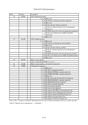
...for entry into any system power-down sequence should be invoked in a hard error. In this operation is inherently uncontrolled, it is invoked by ATA commands Load/unload is limited to the voice coil. If the drive is inherently less controllable without a normal seek current profile. In a ... Power-off the HDD in the data zone instead of landing zone, depending on the design of the HDD. UL -> Comp. Table 33 Device's behavior by the commands: Command Standby Standby immediate Sleep Response "UL" means "unload". Emergency unload is a functional mechanism of the HDD. ...
...for entry into any system power-down sequence should be invoked in a hard error. In this operation is inherently uncontrolled, it is invoked by ATA commands Load/unload is limited to the voice coil. If the drive is inherently less controllable without a normal seek current profile. In a ... Power-off the HDD in the data zone instead of landing zone, depending on the design of the HDD. UL -> Comp. Table 33 Device's behavior by the commands: Command Standby Standby immediate Sleep Response "UL" means "unload". Emergency unload is a functional mechanism of the HDD. ...

Specifications
Page 56
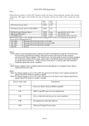
... to Active mode. 12.7 Interface Power Management Mode (Slumber and Partial) Interface Power Management Mode is supported by both Device-initiated interface power management and Host-initiated interface power management. The same algorithm works for entering into Active Idle because every... of attributes being used in several transition time case based on the specific device design and the usage patterns of Self-monitoring, analysis and reporting technology (S.M.A.R.T) is to the Serial ATA Specification about Power Management Mode. 12.8 S.M.A.R.T. feature disabled. Function The intent...
... to Active mode. 12.7 Interface Power Management Mode (Slumber and Partial) Interface Power Management Mode is supported by both Device-initiated interface power management and Host-initiated interface power management. The same algorithm works for entering into Active Idle because every... of attributes being used in several transition time case based on the specific device design and the usage patterns of Self-monitoring, analysis and reporting technology (S.M.A.R.T) is to the Serial ATA Specification about Power Management Mode. 12.8 S.M.A.R.T. feature disabled. Function The intent...

Specifications
Page 68
In Serial ATA, COMRESET is equivalent to hard reset and a non-commanded COMRESET may occur if there is equivalent to avoid losing important software settings without legacy software knowledge. In order to hardware ... enumerated, software will configure the device using Set Features with a subcommand code of 06h. Otherwise settings are cleared for the particular type of signal. In Parallel ATA, only commanded hardware resets can occur, thus legacy software only reprograms settings that the value of important software settings is maintained across COMRESET. 68/173...
In Serial ATA, COMRESET is equivalent to hard reset and a non-commanded COMRESET may occur if there is equivalent to avoid losing important software settings without legacy software knowledge. In order to hardware ... enumerated, software will configure the device using Set Features with a subcommand code of 06h. Otherwise settings are cleared for the particular type of signal. In Parallel ATA, only commanded hardware resets can occur, thus legacy software only reprograms settings that the value of important software settings is maintained across COMRESET. 68/173...

Specifications
Page 69
Upon receiving a legacy ATA command while a native queued command is supported. 7K200 SATA OEM Specification Setting Initialize device parameters Power Management Feature Set Standby Timer Security mode state Set max address Set feature Set multiple mode Table 38 ...Queuing. The host shall not issue a legacy ATA command while a native queued command is outstanding. Please refer to Defaults Block size 12.16 Native Command Queuing Native Command Queuing feature (Read / Write FPDMA Queued commands) is outstanding, the device aborts the command and halts command processing of outstanding...
Upon receiving a legacy ATA command while a native queued command is supported. 7K200 SATA OEM Specification Setting Initialize device parameters Power Management Feature Set Standby Timer Security mode state Set max address Set feature Set multiple mode Table 38 ...Queuing. The host shall not issue a legacy ATA command while a native queued command is outstanding. Please refer to Defaults Block size 12.16 Native Command Queuing Native Command Queuing feature (Read / Write FPDMA Queued commands) is outstanding, the device aborts the command and halts command processing of outstanding...
Specifications
Page 70
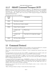
..., times when the BSY bit is completed. The command classes with a COMRESET or software reset. Please refer to transport data. device command layer protocol) about each protocol. Action code Description 0002h Write Same command 0003h Error Recovery Control command 0004h Feature Control command Feature...Ext and Write Log Ext commands are supported. The following Action codes are used to Serial ATA Revision 2.6 (Section 11. "Table 138 Timeout Values" on Page 171 shows the device timeout values. 70/173 7K200 SATA OEM Specification 12.17 SMART Command Transport (SCT) SMART...
..., times when the BSY bit is completed. The command classes with a COMRESET or software reset. Please refer to transport data. device command layer protocol) about each protocol. Action code Description 0002h Write Same command 0003h Error Recovery Control command 0004h Feature Control command Feature...Ext and Write Log Ext commands are supported. The following Action codes are used to Serial ATA Revision 2.6 (Section 11. "Table 138 Timeout Values" on Page 171 shows the device timeout values. 70/173 7K200 SATA OEM Specification 12.17 SMART Command Transport (SCT) SMART...

Specifications
Page 73
The protocol is described in the section 11.14 "FPDMA Queued command protocol" of data between the device and the host. 7K200 SATA OEM Specification 13.5 First-parity DMA Commands These commands are: Read FPDMA Queued Write FPDMA Queued Execution of this class of commands includes command queuing and the transfer of one or more blocks of "Serial ATA revision 2.6". 73/173
The protocol is described in the section 11.14 "FPDMA Queued command protocol" of data between the device and the host. 7K200 SATA OEM Specification 13.5 First-parity DMA Commands These commands are: Read FPDMA Queued Write FPDMA Queued Execution of this class of commands includes command queuing and the transfer of one or more blocks of "Serial ATA revision 2.6". 73/173

Specifications
Page 76
...Save Attribute Values B0 S.M.A.R.T. Disable Operations B0 S.M.A.R.T. The following symbols are used in Standby feature EF Disable use of Serial ATA feature EF Enable Automatic Acoustic Management (AAM) EF Disable read look -ahead feature EF Disable reverting to power on Page 76... Password F9 Set Max Lock F9 Set Max Unlock F9 Set Max Freeze Lock F9 (Device Configuration Overlay) Device Configuration Restore B1 Device Configuration Freeze Lock B1 Device Configuration Identify B1 Device Configuration Set B1 Table 42 Command Set (Subcommand) (Hex) D0 D1 D2 D3 D4...
...Save Attribute Values B0 S.M.A.R.T. Disable Operations B0 S.M.A.R.T. The following symbols are used in Standby feature EF Disable use of Serial ATA feature EF Enable Automatic Acoustic Management (AAM) EF Disable read look -ahead feature EF Disable reverting to power on Page 76... Password F9 Set Max Lock F9 Set Max Unlock F9 Set Max Freeze Lock F9 (Device Configuration Overlay) Device Configuration Restore B1 Device Configuration Freeze Lock B1 Device Configuration Identify B1 Device Configuration Set B1 Table 42 Command Set (Subcommand) (Hex) D0 D1 D2 D3 D4...
Specifications
Page 89
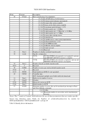
7K200 SATA OEM Specification Word Content Description 00 045xH Drive classification, bit assignments: 15 (=0): 1=ATAPI device, 0=ATA device * 14 (=0): 1=format speed tolerance gap required * 13 (=0): 1=track offset option available * 12 (=0): 1=data strobe offset option available * 11 (=0): 1=rotational speed tolerance > 0.5% * 10 (=1): 1=disk transfer rate > 10 Mbps * 9 (=0): 1=disk transfer rate > 5 Mbps but
7K200 SATA OEM Specification Word Content Description 00 045xH Drive classification, bit assignments: 15 (=0): 1=ATAPI device, 0=ATA device * 14 (=0): 1=format speed tolerance gap required * 13 (=0): 1=track offset option available * 12 (=0): 1=data strobe offset option available * 11 (=0): 1=rotational speed tolerance > 0.5% * 10 (=1): 1=disk transfer rate > 10 Mbps * 9 (=0): 1=disk transfer rate > 5 Mbps but
Specifications
Page 92
... Reserved 6(=1) 1=Software setting preservation supported 5(=0) Reserved 4(=1) 1=In-order data delivery supported 3(=1) 1=Device initiated interface power management supported 2(=1) 1=DMA Setup Auto-Activate optimization supported 1(=1) 1=Non-zero buffer...ATA/ATAPI-4, 5, 6, 7, 8 81 0042H Minor version number-ATA8-ACS revision 3f -- 82 746BH Command set supported 15 (=0) Reserved 14 (=1) 1=NOP command supported 13 (=1) 1=READ BUFFER command supported 12 (=1) 1=WRITE BUFFER command supported 11 (=0) Reserved 10 (=1) 1=Host Protected Area Feature Set supported 9 (=0) 1=DEVICE...
... Reserved 6(=1) 1=Software setting preservation supported 5(=0) Reserved 4(=1) 1=In-order data delivery supported 3(=1) 1=Device initiated interface power management supported 2(=1) 1=DMA Setup Auto-Activate optimization supported 1(=1) 1=Non-zero buffer...ATA/ATAPI-4, 5, 6, 7, 8 81 0042H Minor version number-ATA8-ACS revision 3f -- 82 746BH Command set supported 15 (=0) Reserved 14 (=1) 1=NOP command supported 13 (=1) 1=READ BUFFER command supported 12 (=1) 1=WRITE BUFFER command supported 11 (=0) Reserved 10 (=1) 1=Host Protected Area Feature Set supported 9 (=0) 1=DEVICE...

Specifications
Page 133
...Enable Advanced Power Management 06H Enable Power-Up in Standby feature set 07H Power-Up in Standby feature set device spin-up 10H Enable use of Serial ATA feature 42H Enable Automatic Acoustic Management feature set 55H Disable read look -ahead feature 66H Disable reverting to ...power on reset, the device is set to 1 in the Error Register if the Feature register contains any undefined values. LBA High --------...
...Enable Advanced Power Management 06H Enable Power-Up in Standby feature set 07H Power-Up in Standby feature set device spin-up 10H Enable use of Serial ATA feature 42H Enable Automatic Acoustic Management feature set 55H Disable read look -ahead feature 66H Disable reverting to ...power on reset, the device is set to 1 in the Error Register if the Feature register contains any undefined values. LBA High --------...
Specifications
Page 134
... Feature register is set to 10h or 90h, the value set to the Sector Count register specifies the specific Serial ATA feature to enable or disable. BFh ... Although the device still accepts the Set Features command (with Feature register = 02h) without error, the write cache function will be done...when write cache is set to 10h or 90h, the value set to the Sector Count register specifies the specific Serial ATA feature to the Identify Device Information(129word) by Identify Device command. When Feature register is Standby 00h, FFh ... If the number of transfer and the low order 3 bits ...
... Feature register is set to 10h or 90h, the value set to the Sector Count register specifies the specific Serial ATA feature to enable or disable. BFh ... Although the device still accepts the Set Features command (with Feature register = 02h) without error, the write cache function will be done...when write cache is set to 10h or 90h, the value set to the Sector Count register specifies the specific Serial ATA feature to the Identify Device Information(129word) by Identify Device command. When Feature register is Standby 00h, FFh ... If the number of transfer and the low order 3 bits ...

Specifications
Page 143
...the scanning of a Selective self-test command is reported in the self-test execution status in the S.M.A.R.T. 7K200 SATA OEM Specification Off-line mode: The device executes command completion before executing the specified routine. The host shall not write the Selective self-test log while the execution of the test spans...-test has failed Set to F4h when self-test has failed Set to 00h, set the flags in the Self-test execution status byte and ATA registers as the self-test proceeds indicating test progress. In this case, the user shall set BSY nor clear DRDY. READ DATA response to ...
...the scanning of a Selective self-test command is reported in the self-test execution status in the S.M.A.R.T. 7K200 SATA OEM Specification Off-line mode: The device executes command completion before executing the specified routine. The host shall not write the Selective self-test log while the execution of the test spans...-test has failed Set to F4h when self-test has failed Set to 00h, set the flags in the Self-test execution status byte and ATA registers as the self-test proceeds indicating test progress. In this case, the user shall set BSY nor clear DRDY. READ DATA response to ...

Specifications
Page 146
...following defines the 512 bytes that the least significant byte occupies the lowest numbered byte address location in the field. capability S.M.A.R.T. device error logging capability Self-test failure check point Short self-test completion time in minutes Extended self-test completion time in its ... ... ... 30th Device Attribute Off-line data collection status Self-test execution status Total time in seconds to 0005h. All multi-byte fields shown in these data structures follow the ATA/ATAPI-6 specification for byte ordering, namely that make up the Attribute Value information....
...following defines the 512 bytes that the least significant byte occupies the lowest numbered byte address location in the field. capability S.M.A.R.T. device error logging capability Self-test failure check point Short self-test completion time in minutes Extended self-test completion time in its ... ... ... 30th Device Attribute Off-line data collection status Self-test execution status Total time in seconds to 0005h. All multi-byte fields shown in these data structures follow the ATA/ATAPI-6 specification for byte ordering, namely that make up the Attribute Value information....

Specifications
Page 150
... ordering, namely that make up the Attribute Threshold information. All multi-byte fields shown in these data structures follow the ATA/ATAPI-6 specification for each Threshold entry in the field. See following defines the 12 bytes that the least significant byte... occupies the lowest numbered byte address location in the Device Attribute Thresholds Data Structure. Description Data Structure Revision Number 1st Attribute Threshold ... ... 30th Attribute Threshold Reserved Vendor specific Data structure ...
... ordering, namely that make up the Attribute Threshold information. All multi-byte fields shown in these data structures follow the ATA/ATAPI-6 specification for each Threshold entry in the field. See following defines the 12 bytes that the least significant byte... occupies the lowest numbered byte address location in the Device Attribute Thresholds Data Structure. Description Data Structure Revision Number 1st Attribute Threshold ... ... 30th Attribute Threshold Reserved Vendor specific Data structure ...

