

Specifications
Page 6
... 35 Table 21. Continued --- 94 Table 58 Identify device information --- Nonoperating shock 35 Table 22. Continued --- 101 Table 64 Number of cylinders/heads/sectors by ATA commands 53 Table 34 Power conditions 55 Table 35 Command table for device lock operation 63 Table 36 Command table for HTS5432XXL9SA00 / HTS5432XXL9A300 102 Table...
... 35 Table 21. Continued --- 94 Table 58 Identify device information --- Nonoperating shock 35 Table 22. Continued --- 101 Table 64 Number of cylinders/heads/sectors by ATA commands 53 Table 34 Power conditions 55 Table 35 Command table for device lock operation 63 Table 36 Command table for HTS5432XXL9SA00 / HTS5432XXL9A300 102 Table...
Specifications
Page 9
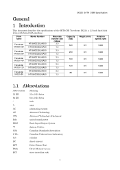
5K320 SATA OEM Specification General 1 Introduction This document describes the specifications of the HITACHI Travelstar 5K320, a 2.5-inch hard disk drive with Serial ATA interface: Drive name Travelstar 5K320-320 Model Number HTS543232L9A300 HTS543232L9SA00 Max data transfer rate (Gbps) 3.0 1.5 Capacity (GB) 320 Height (mm... 1.5 5400 Travelstar HTS543280L9A300 3.0 80 9.5 5400 5K320-80 HTS543280L9SA00 1.5 1.1 Abbreviations Abbreviation 32 KB 64 KB " A AC AT ATA Bels BIOS °C CSA C-UL Cyl DC DFT DMA ECC Meaning 32 x 1024 bytes 64 x 1024 bytes inch amp alternating...
5K320 SATA OEM Specification General 1 Introduction This document describes the specifications of the HITACHI Travelstar 5K320, a 2.5-inch hard disk drive with Serial ATA interface: Drive name Travelstar 5K320-320 Model Number HTS543232L9A300 HTS543232L9SA00 Max data transfer rate (Gbps) 3.0 1.5 Capacity (GB) 320 Height (mm... 1.5 5400 Travelstar HTS543280L9A300 3.0 80 9.5 5400 5K320-80 HTS543280L9SA00 1.5 1.1 Abbreviations Abbreviation 32 KB 64 KB " A AC AT ATA Bels BIOS °C CSA C-UL Cyl DC DFT DMA ECC Meaning 32 x 1024 bytes 64 x 1024 bytes inch amp alternating...

Specifications
Page 12
... surface of the user 1.4 Drive handling precautions Do not press on the top cover (See figure below ). 5K320 SATA OEM Specification 1.2 References Serial ATA International Organization : Serial ATA Revision 2.6 1.3 General caution Do not apply force to the drive after removing it from the shipping package and the ESD protective bag are the...
... surface of the user 1.4 Drive handling precautions Do not press on the top cover (See figure below ). 5K320 SATA OEM Specification 1.2 References Serial ATA International Organization : Serial ATA Revision 2.6 1.3 General caution Do not apply force to the drive after removing it from the shipping package and the ESD protective bag are the...
Specifications
Page 13
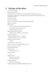
... actuator servo (Embedded Sector Servo) Rotary voice coil motor actuator Load/Unload mechanism Mechanical latch 0.55 Watts at idle state Power on to Serial ATA International Organization: Serial ATA Revision 2.6(15-February-2007) Integrated controller No-ID recording format Coding : 100/102 2bit parity (199/200 RC Modulation Encoding) Multi zone recording...
... actuator servo (Embedded Sector Servo) Rotary voice coil motor actuator Load/Unload mechanism Mechanical latch 0.55 Watts at idle state Power on to Serial ATA International Organization: Serial ATA Revision 2.6(15-February-2007) Integrated controller No-ID recording format Coding : 100/102 2bit parity (199/200 RC Modulation Encoding) Multi zone recording...
Specifications
Page 29
...; ECC implementation On-the-fly correction performed as a part of read channel function recovers up to 16 symbols of the drive should satisfy Serial ATA Revision 2.6. The power-off sequence of error in 1 sector (1 symbol is routed on top or comes in contact with the 6.3.6.2,"Required power-off...
...; ECC implementation On-the-fly correction performed as a part of read channel function recovers up to 16 symbols of the drive should satisfy Serial ATA Revision 2.6. The power-off sequence of error in 1 sector (1 symbol is routed on top or comes in contact with the 6.3.6.2,"Required power-off...

Specifications
Page 40
... power P15 V12 12V power Table 23. If pin P11 is used . Signal S4 Gnd S5 B- 2nd mate Differential signal B from Phy S3 A- Serial ATA: High Speed Serialized AT Attachment Revision 1.0a 7-January -2003 40 Interface connector pins and I/O signals Signal Gnd RX+ RXGnd TXTX+ Gnd 3.3V 3.3V 3.... I/O Input Input Output Output Note 1; 5K320 SATA OEM Specification 7.3 Signal definitions The pin assignments of interface signals are connected to the serial ATA cable 7.3.2 RX+ / RX- These signals are the inbound high-speed differential signals that are connected to the serial...
... power P15 V12 12V power Table 23. If pin P11 is used . Signal S4 Gnd S5 B- 2nd mate Differential signal B from Phy S3 A- Serial ATA: High Speed Serialized AT Attachment Revision 1.0a 7-January -2003 40 Interface connector pins and I/O signals Signal Gnd RX+ RXGnd TXTX+ Gnd 3.3V 3.3V 3.... I/O Input Input Output Output Note 1; 5K320 SATA OEM Specification 7.3 Signal definitions The pin assignments of interface signals are connected to the serial ATA cable 7.3.2 RX+ / RX- These signals are the inbound high-speed differential signals that are connected to the serial...

Specifications
Page 45
ATA/ATAPI Command Set (ATA8-ACS) Revision 3f dated on 11 December 2006 HTS5432XXL9SA00 / HTS5432XXL9A300 support following Working Document of HTS5432XXL9SA00 / HTS5432XXL9A300. The interface ...Host INTRQ Device indicates HTS5432XXL9SA00 / HTS5432XXL9A300 Host indicates the system that the device is attached to. Interrupt request (Device or Host) - 45 - Serial ATA International Organization : Serial ATA Revision 2.6 dated on 15 February 2007 AT Attachment 8 - 8 General 5K320 SATA OEM Specification 8.1 Introduction This specification describes the host interface of Information ...
ATA/ATAPI Command Set (ATA8-ACS) Revision 3f dated on 11 December 2006 HTS5432XXL9SA00 / HTS5432XXL9A300 support following Working Document of HTS5432XXL9SA00 / HTS5432XXL9A300. The interface ...Host INTRQ Device indicates HTS5432XXL9SA00 / HTS5432XXL9A300 Host indicates the system that the device is attached to. Interrupt request (Device or Host) - 45 - Serial ATA International Organization : Serial ATA Revision 2.6 dated on 15 February 2007 AT Attachment 8 - 8 General 5K320 SATA OEM Specification 8.1 Introduction This specification describes the host interface of Information ...

Specifications
Page 46
... command does not support 80h as the return value. 10 Physical Interface Physical Interface is described in Functional Specification part. 11 Registers In Serial ATA, the host adapter contains a set of registers that shadow the contents of Information Technology, AT Attachment 8 - Shadow Register Block registers are...the following cases, the host adapter sets the BSY bit in its shadow Status Register and transmits a FIS to as follows: S.M.A.R.T. ATA/ATAPI Command Set (ATA/ATAPI8-ACS) Revision 3f dated 11 Dec. 2006, with a change of state of the SRST bit COMRESET is written in...
... command does not support 80h as the return value. 10 Physical Interface Physical Interface is described in Functional Specification part. 11 Registers In Serial ATA, the host adapter contains a set of registers that shadow the contents of Information Technology, AT Attachment 8 - Shadow Register Block registers are...the following cases, the host adapter sets the BSY bit in its shadow Status Register and transmits a FIS to as follows: S.M.A.R.T. ATA/ATAPI Command Set (ATA/ATAPI8-ACS) Revision 3f dated 11 Dec. 2006, with a change of state of the SRST bit COMRESET is written in...

Specifications
Page 47
Serial ATA register name Register name in this specification when writing registers Features Feature current Features (exp) Feature previous...be set " on page 75. The command set is shown in this register is different from that uses in the Serial ATA 2.6 specification. All other registers required for the Command Block Registers as the ATA8-ACS standard. Command execution begins immediately after ... the corresponding of the register names used in this specification with those used in the Serial ATA 2.6 specification. However, the register naming convention is written.
Serial ATA register name Register name in this specification when writing registers Features Feature current Features (exp) Feature previous...be set " on page 75. The command set is shown in this register is different from that uses in the Serial ATA 2.6 specification. All other registers required for the Command Block Registers as the ATA8-ACS standard. Command execution begins immediately after ... the corresponding of the register names used in this specification with those used in the Serial ATA 2.6 specification. However, the register naming convention is written.

Specifications
Page 51
...the device to revert these parameters to the power on defaults. (*4) In the case of CHS (set , then is issued in Serial ATA bus. Read look-ahead - In other mechanical parametric, and sets default values. The device resets the interface circuitry according to the initial ...case, the device does not change current mode. (*5) According to the Set Features requirement. The actions of each reset are three types of reset in ATA as follows: Power On Reset (POR) The device executes a series of registers (*2) O o o Reverting programmed parameters to standby mode. Multiple mode...
...the device to revert these parameters to the power on defaults. (*4) In the case of CHS (set , then is issued in Serial ATA bus. Read look-ahead - In other mechanical parametric, and sets default values. The device resets the interface circuitry according to the initial ...case, the device does not change current mode. (*5) According to the Set Features requirement. The actions of each reset are three types of reset in ATA as follows: Power On Reset (POR) The device executes a series of registers (*2) O o o Reverting programmed parameters to standby mode. Multiple mode...
Specifications
Page 53
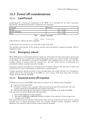
... error. Heads possibly land in the following order: 1. This power-down state, or system suspend state, or system hibernation state. It is controlled by ATA commands Load/unload is unavailable to 350 ms in rare situations. The actuator velocity is greater than a normal unload. UL -> Comp. Examples: Data loss...
... error. Heads possibly land in the following order: 1. This power-down state, or system suspend state, or system hibernation state. It is controlled by ATA commands Load/unload is unavailable to 350 ms in rare situations. The actuator velocity is greater than a normal unload. UL -> Comp. Examples: Data loss...

Specifications
Page 57
... to enter Active Idle mode is variable depending on the specific device design and the usage patterns of ABLE-2. The optimal time to the Serial ATA Specification about Power Management Mode. 12.8 S.M.A.R.T. 12.6.4 Transition Time 5K320 SATA OEM Specification The transition time is dynamically managed by Set Feature Enable Advanced Power...
... to enter Active Idle mode is variable depending on the specific device design and the usage patterns of ABLE-2. The optimal time to the Serial ATA Specification about Power Management Mode. 12.8 S.M.A.R.T. 12.6.4 Transition Time 5K320 SATA OEM Specification The transition time is dynamically managed by Set Feature Enable Advanced Power...

Specifications
Page 69
... preservation may occur if there is an asynchronous loss of signal. In order to avoid losing important software settings without legacy software knowledge. In Serial ATA, COMRESET is equivalent to hardware reset, in the case of an asynchronous loss of signal some software settings may be enabled or disabled using Set...
... preservation may occur if there is an asynchronous loss of signal. In order to avoid losing important software settings without legacy software knowledge. In Serial ATA, COMRESET is equivalent to hardware reset, in the case of an asynchronous loss of signal some software settings may be enabled or disabled using Set...
Specifications
Page 70
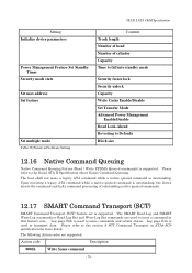
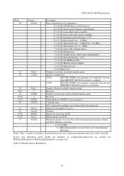
... (Read / Write FPDMA Queued commands) is supported. Action code Description 0002h Write Same command - 70 - Upon receiving a legacy ATA command while a native queued command is outstanding, the device aborts the command and halts command processing of cylinder Capacity Time to fall ... Advanced Power Management Enable/Disable Read Look-Ahead Reverting to issue commands and return status. Please refer to the Serial ATA II Specification about Native Command Queuing. 5K320 SATA OEM Specification Setting Initialize device parameters Power Management Feature Set Standby Timer ...
... (Read / Write FPDMA Queued commands) is supported. Action code Description 0002h Write Same command - 70 - Upon receiving a legacy ATA command while a native queued command is outstanding, the device aborts the command and halts command processing of cylinder Capacity Time to fall ... Advanced Power Management Enable/Disable Read Look-Ahead Reverting to issue commands and return status. Please refer to the Serial ATA II Specification about Native Command Queuing. 5K320 SATA OEM Specification Setting Initialize device parameters Power Management Feature Set Standby Timer ...

Specifications
Page 72
... as a device that the status data for a sector of writing to the Command register while BSY=1 or DRQ=1 is changed from the device to Serial ATA Revision 2.6 (Section 11. The INTRQ signal is used by the device to signal most, but not all, times when the BSY bit is unpredictable and...
... as a device that the status data for a sector of writing to the Command register while BSY=1 or DRQ=1 is changed from the device to Serial ATA Revision 2.6 (Section 11. The INTRQ signal is used by the device to signal most, but not all, times when the BSY bit is unpredictable and...

Specifications
Page 74
... the transfer of one or more blocks of the DMA transfer commands is described in the section 11.14 "FPDMA Queued command protocol" of "Serial ATA revision 2.6". 74 The protocol is identical to the Read Sector or Write Sector commands except that the host initializes the slave-DMA channel prior to...
... the transfer of one or more blocks of the DMA transfer commands is described in the section 11.14 "FPDMA Queued command protocol" of "Serial ATA revision 2.6". 74 The protocol is identical to the Read Sector or Write Sector commands except that the host initializes the slave-DMA channel prior to...

Specifications
Page 77
... Mode Enable Advanced Power Management feature Enable Power-Up in Standby feature Power-Up in Standby feature device Spin-Up Enable use of Serial ATA feature Disable read look-ahead feature Enable reverting to power on defaults Disable write cache Disable Advanced Power Management feature Disable Power-Up in... " on Page 75 shows the commands that the head number part of the Device Register is used in Standby feature Disable use of Serial ATA feature Enable read look-ahead feature Disable reverting to power on defaults (Set Max security extension) Set Max Set Password Set Max Lock Set...
... Mode Enable Advanced Power Management feature Enable Power-Up in Standby feature Power-Up in Standby feature device Spin-Up Enable use of Serial ATA feature Disable read look-ahead feature Enable reverting to power on defaults Disable write cache Disable Advanced Power Management feature Disable Power-Up in... " on Page 75 shows the commands that the head number part of the Device Register is used in Standby feature Disable use of Serial ATA feature Enable read look-ahead feature Disable reverting to power on defaults (Set Max security extension) Set Max Set Password Set Max Lock Set...
Specifications
Page 92
5K320 SATA OEM Specification Word Content Description 00 045xH Drive classification, bit assignments: 15 (=0): 1=ATAPI device, 0=ATA device * 14 (=0): 1=format speed tolerance gap required * 13 (=0): 1=track offset option available * 12 (=0): 1=data strobe offset option available * 11 (=0): 1=rotational speed tolerance > 0.5% * 10 (=1): 1=disk transfer rate > 10 Mbps * 9 (=0): 1=disk transfer rate > 5 Mbps but
5K320 SATA OEM Specification Word Content Description 00 045xH Drive classification, bit assignments: 15 (=0): 1=ATAPI device, 0=ATA device * 14 (=0): 1=format speed tolerance gap required * 13 (=0): 1=track offset option available * 12 (=0): 1=data strobe offset option available * 11 (=0): 1=rotational speed tolerance > 0.5% * 10 (=1): 1=disk transfer rate > 10 Mbps * 9 (=0): 1=disk transfer rate > 5 Mbps but
Specifications
Page 95
... interface power management enabled 2(=x) 1=DMA Setup Auto-Activate optimization enabled 1(=x) 1=Non-zero buffer offset in DMA Setup FIS enabled 0(=0) Reserved 80 01FCH Major version number ATA-2.3 and ATA/ATAPI-4, 5, 6, 7, 8 81 0042H Minor version number-ATA8-ACS revision 3f -- 82 746BH Command set supported 15 (=0) Reserved 14 (=1) 1=NOP command supported 13 (=1) 1=READ BUFFER...
... interface power management enabled 2(=x) 1=DMA Setup Auto-Activate optimization enabled 1(=x) 1=Non-zero buffer offset in DMA Setup FIS enabled 0(=0) Reserved 80 01FCH Major version number ATA-2.3 and ATA/ATAPI-4, 5, 6, 7, 8 81 0042H Minor version number-ATA8-ACS revision 3f -- 82 746BH Command set supported 15 (=0) Reserved 14 (=1) 1=NOP command supported 13 (=1) 1=READ BUFFER...

Specifications
Page 137
...set to 1 in below table. Feature VVVVVVVV Sector Count Note.1 LBA Low -------- LBA Low -------- ABT will be set 90H Disable use of Serial ATA feature AAH Enable read look-ahead feature 66H Disable reverting to power on defaults Note 1. 137 LBA Mid -------- Write cache ECC bytes Read look-... 06H Enable Power-Up in Standby feature set 07H Power-Up in Standby feature set device spin-up 10H Enable use of Serial ATA feature 55H Disable read look-ahead feature CCH Enable reverting to establish the following features as shown in the Error Register if the ...
...set to 1 in below table. Feature VVVVVVVV Sector Count Note.1 LBA Low -------- LBA Low -------- ABT will be set 90H Disable use of Serial ATA feature AAH Enable read look-ahead feature 66H Disable reverting to power on defaults Note 1. 137 LBA Mid -------- Write cache ECC bytes Read look-... 06H Enable Power-Up in Standby feature set 07H Power-Up in Standby feature set device spin-up 10H Enable use of Serial ATA feature 55H Disable read look-ahead feature CCH Enable reverting to establish the following features as shown in the Error Register if the ...
