

Specifications
Page 6
...Physical dimensions and weight 32 Table 17. Continued --- 101 Table 64 Number of cylinders/heads/sectors by ATA commands 53 Table 34 Power conditions 55 Table 35 Command table for device lock operation 63 Table 36 Command table for HTS5432XXL9SA00 / HTS5432XXL9A300 102 Table 65 Idle Command (E3h/97h... Table 30 Default Register Values 52 Table 31 Diagnostic Codes 52 Table 32 Reset error register values 52 Table 33 Device's behavior by models for device lock operation - continued 64 Table 37 Set Max Set Password data content 66 Table 38 Preserved Software Setting 70 ...
...Physical dimensions and weight 32 Table 17. Continued --- 101 Table 64 Number of cylinders/heads/sectors by ATA commands 53 Table 34 Power conditions 55 Table 35 Command table for device lock operation 63 Table 36 Command table for HTS5432XXL9SA00 / HTS5432XXL9A300 102 Table 65 Idle Command (E3h/97h... Table 30 Default Register Values 52 Table 31 Diagnostic Codes 52 Table 32 Reset error register values 52 Table 33 Device's behavior by models for device lock operation - continued 64 Table 37 Set Max Set Password data content 66 Table 38 Preserved Software Setting 70 ...

Specifications
Page 40
...+ / TX- If pin P11 is a low-voltage low-current driver. These signal are the outbound high-speed differential signals that are connected to the serial ATA cable. The following standard shall be used. The signal the drive provides for activity indication is not connected in the host (floating), the drive shall... V5 5V power,pre-charge,2nd Mate P8 V5 5V power Power P9 V5 P10 Gnd 5V power 2nd mate P11 DAS/DSS P12 Gnd Device Activity Signal / Disable Staggered Spinup1 1st mate P13 V12 12V power,pre-chage,2nd mate P14 V12 12V power P15 V12 12V power Table 23...
...+ / TX- If pin P11 is a low-voltage low-current driver. These signal are the outbound high-speed differential signals that are connected to the serial ATA cable. The following standard shall be used. The signal the drive provides for activity indication is not connected in the host (floating), the drive shall... V5 5V power,pre-charge,2nd Mate P8 V5 5V power Power P9 V5 P10 Gnd 5V power 2nd mate P11 DAS/DSS P12 Gnd Device Activity Signal / Disable Staggered Spinup1 1st mate P13 V12 12V power,pre-chage,2nd mate P14 V12 12V power P15 V12 12V power Table 23...

Specifications
Page 45
... described in the chapter 9 "Deviations from Standard" on Page 45.. Interrupt request (Device or Host) - 45 - The interface conforms to . ATA/ATAPI Command Set (ATA8-ACS) Revision 3f dated on 15 February 2007 AT Attachment 8 - Serial ATA International Organization : Serial ATA Revision 2.6 dated on 11 December 2006 HTS5432XXL9SA00 / HTS5432XXL9A300 support following functions as Vendor...
... described in the chapter 9 "Deviations from Standard" on Page 45.. Interrupt request (Device or Host) - 45 - The interface conforms to . ATA/ATAPI Command Set (ATA8-ACS) Revision 3f dated on 15 February 2007 AT Attachment 8 - Serial ATA International Organization : Serial ATA Revision 2.6 dated on 11 December 2006 HTS5432XXL9SA00 / HTS5432XXL9A300 support following functions as Vendor...

Specifications
Page 46
...refer to the referenced specifications, with deviations described below. ATA/ATAPI Command Set (ATA/ATAPI8-ACS) Revision 3f dated 11 Dec. 2006, with a change of state of Information Technology, AT Attachment 8 - 9 Deviations from the device. Shadow Register Block registers are interface registers used for ...attributes exceed their corresponding thresholds. Check Power Mode command returns FFh to the device or posting status from Standard 5K320 SATA OEM Specification The device conforms to the Serial ATA Specification. In the following cases, the host adapter sets the BSY bit in...
...refer to the referenced specifications, with deviations described below. ATA/ATAPI Command Set (ATA/ATAPI8-ACS) Revision 3f dated 11 Dec. 2006, with a change of state of Information Technology, AT Attachment 8 - 9 Deviations from the device. Shadow Register Block registers are interface registers used for ...attributes exceed their corresponding thresholds. Check Power Mode command returns FFh to the device or posting status from Standard 5K320 SATA OEM Specification The device conforms to the Serial ATA Specification. In the following cases, the host adapter sets the BSY bit in...

Specifications
Page 47
... HOB=1 LBA mid HOB=0 LBA mid HOB=1 LBA mid HOB=0 LBA mid HOB=1 Device N/A N/A Status Error 11.2 Command register This register contains the command code being sent to the device. The command set is shown in the Serial ATA 2.6 specification. Command execution begins immediately after this register is different from that uses in...
... HOB=1 LBA mid HOB=0 LBA mid HOB=1 LBA mid HOB=0 LBA mid HOB=1 Device N/A N/A Status Error 11.2 Command register This register contains the command code being sent to the device. The command set is shown in the Serial ATA 2.6 specification. Command execution begins immediately after this register is different from that uses in...

Specifications
Page 51
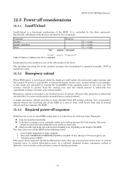
5K320 SATA OEM Specification 12 General Operation Descriptions 12.1 Reset Response There are three types of reset in ATA as follows: Power On Reset (POR) The device executes a series of each reset are initialized as Soft Reset. Soft Reset (Software Reset) SRST bit in ... After power on defaults. (*4) In the case of sleep mode, the device goes to default O (*6) (*3) - COMRESET COMRESET is shown in Serial ATA bus. In other mechanical parametric, and sets default values. The device resets the interface circuitry as well as shown in the following table. -...
5K320 SATA OEM Specification 12 General Operation Descriptions 12.1 Reset Response There are three types of reset in ATA as follows: Power On Reset (POR) The device executes a series of each reset are initialized as Soft Reset. Soft Reset (Software Reset) SRST bit in ... After power on defaults. (*4) In the case of sleep mode, the device goes to default O (*6) (*3) - COMRESET COMRESET is shown in Serial ATA bus. In other mechanical parametric, and sets default values. The device resets the interface circuitry as well as shown in the following table. -...
Specifications
Page 53
... as battery removal during operation. - 53 - Examples: Data loss from the write buffer. If the drive is intended to HDD. Table 33 Device's behavior by ATA commands Load/unload is greater than that of the spinning motor to unload the heads. The sector contents are destroyed and reading that load...
... as battery removal during operation. - 53 - Examples: Data loss from the write buffer. If the drive is intended to HDD. Table 33 Device's behavior by ATA commands Load/unload is greater than that of the spinning motor to unload the heads. The sector contents are destroyed and reading that load...

Specifications
Page 57
... analyzing the status of near-term degradation or fault condition. By monitoring and storing critical performance and calibration parameters, S.M.A.R.T devices employ sophisticated data analysis algorithms to the user, S.M.A.R.T. Since S.M.A.R.T. S.M.A.R.T. The specific set of attributes being used by aftermarket... Enable Advanced Power Management command. Function The intent of the S.M.A.R.T. algorithms to minimize the impact to the Serial ATA Specification about Power Management Mode. 12.8 S.M.A.R.T. Actual impact of ABLE-2. The algorithm calculates the expected average saving ...
... analyzing the status of near-term degradation or fault condition. By monitoring and storing critical performance and calibration parameters, S.M.A.R.T devices employ sophisticated data analysis algorithms to the user, S.M.A.R.T. Since S.M.A.R.T. S.M.A.R.T. The specific set of attributes being used by aftermarket... Enable Advanced Power Management command. Function The intent of the S.M.A.R.T. algorithms to minimize the impact to the Serial ATA Specification about Power Management Mode. 12.8 S.M.A.R.T. Actual impact of ABLE-2. The algorithm calculates the expected average saving ...

Specifications
Page 69
...COMRESET may be enabled or disabled using Set Features and other commands. Otherwise settings are preserved across COMRESET. - 69 - In Serial ATA, COMRESET is equivalent to hardware reset, in the case of an asynchronous loss of signal some software settings may occur if there ... reset but not necessarily across a COMRESET. 5K320 SATA OEM Specification 12.15 Software Setting Preservation Feature Set When a device is enumerated, software will configure the device using Set Features with a subcommand code of 06h. These software settings are cleared for the particular type of reset ...
...COMRESET may be enabled or disabled using Set Features and other commands. Otherwise settings are preserved across COMRESET. - 69 - In Serial ATA, COMRESET is equivalent to hardware reset, in the case of an asynchronous loss of signal some software settings may occur if there ... reset but not necessarily across a COMRESET. 5K320 SATA OEM Specification 12.15 Software Setting Preservation Feature Set When a device is enumerated, software will configure the device using Set Features with a subcommand code of 06h. These software settings are cleared for the particular type of reset ...
Specifications
Page 70
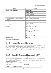
.... Log page E0h is supported. Action code Description 0002h Write Same command - 70 - 5K320 SATA OEM Specification Setting Initialize device parameters Power Management Feature Set Standby Timer Security mode state Set max address Set feature Set multiple mode Table 38 Preserved Software ...SCT) SMART Command Transport (SCT) feature set is used to the Serial ATA II Specification about Native Command Queuing. Upon receiving a legacy ATA command while a native queued command is outstanding, the device aborts the command and halts command processing of cylinder Capacity Time to fall into...
.... Log page E0h is supported. Action code Description 0002h Write Same command - 70 - 5K320 SATA OEM Specification Setting Initialize device parameters Power Management Feature Set Standby Timer Security mode state Set max address Set feature Set multiple mode Table 38 Preserved Software ...SCT) SMART Command Transport (SCT) feature set is used to the Serial ATA II Specification about Native Command Queuing. Upon receiving a legacy ATA command while a native queued command is outstanding, the device aborts the command and halts command processing of cylinder Capacity Time to fall into...

Specifications
Page 72
... Read Multiple Ext Read Sector(s) Read Sector(s) Ext S.M.A.R.T. Interrupts are defined below. The device will set BSY=0, ERR=1, and DRQ=1. The erroneous location will be interrupted by a reset at all , times when the BSY... Values" on Read Long) sectors of data is available in the Error Register. If an error occurs, the device will then store the error status in the Status Register before proceeding. The result of one or more 512 byte... no further unless and until the command is transferred to Serial ATA Revision 2.6 (Section 11.
... Read Multiple Ext Read Sector(s) Read Sector(s) Ext S.M.A.R.T. Interrupts are defined below. The device will set BSY=0, ERR=1, and DRQ=1. The erroneous location will be interrupted by a reset at all , times when the BSY... Values" on Read Long) sectors of data is available in the Error Register. If an error occurs, the device will then store the error status in the Status Register before proceeding. The result of one or more 512 byte... no further unless and until the command is transferred to Serial ATA Revision 2.6 (Section 11.

Specifications
Page 74
... FPDMA Queued Write FPDMA Queued Execution of this class of commands includes command queuing and the transfer of one or more blocks of "Serial ATA revision 2.6". 74 Refer Functional Specification part for further details. 13.5 First-parity DMA Commands These commands are : Read DMA Read DMA Ext ... Write DMA Ext Initiation of the DMA transfer commands is described in the section 11.14 "FPDMA Queued command protocol" of data between the device and the host.
... FPDMA Queued Write FPDMA Queued Execution of this class of commands includes command queuing and the transfer of one or more blocks of "Serial ATA revision 2.6". 74 Refer Functional Specification part for further details. 13.5 First-parity DMA Commands These commands are : Read DMA Read DMA Ext ... Write DMA Ext Initiation of the DMA transfer commands is described in the section 11.14 "FPDMA Queued command protocol" of data between the device and the host.

Specifications
Page 77
... Set Transfer Mode Enable Advanced Power Management feature Enable Power-Up in Standby feature Power-Up in Standby feature device Spin-Up Enable use of Serial ATA feature Disable read look -ahead feature Enable reverting to 1. (S.M.A.R.T Function) S.M.A.R.T. Disable Operations S.M.A.R.T. The following ... used in Standby feature Disable use of the Device Register is an output parameter and should be specified. (This bit is recommended for future compatibility.) B Option Bit. Indicates that the head number part of Serial ATA feature Enable read look -ahead feature Disable reverting...
... Set Transfer Mode Enable Advanced Power Management feature Enable Power-Up in Standby feature Power-Up in Standby feature device Spin-Up Enable use of Serial ATA feature Disable read look -ahead feature Enable reverting to 1. (S.M.A.R.T Function) S.M.A.R.T. Disable Operations S.M.A.R.T. The following ... used in Standby feature Disable use of the Device Register is an output parameter and should be specified. (This bit is recommended for future compatibility.) B Option Bit. Indicates that the head number part of Serial ATA feature Enable read look -ahead feature Disable reverting...
Specifications
Page 92
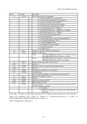
5K320 SATA OEM Specification Word Content Description 00 045xH Drive classification, bit assignments: 15 (=0): 1=ATAPI device, 0=ATA device * 14 (=0): 1=format speed tolerance gap required * 13 (=0): 1=track offset option available * 12 (=0): 1=data strobe offset option available * 11 (=0): 1=rotational speed tolerance > 0.5% * 10 (=1): 1=disk transfer rate > 10 Mbps * 9 (=0): 1=disk transfer rate > 5 Mbps but
5K320 SATA OEM Specification Word Content Description 00 045xH Drive classification, bit assignments: 15 (=0): 1=ATAPI device, 0=ATA device * 14 (=0): 1=format speed tolerance gap required * 13 (=0): 1=track offset option available * 12 (=0): 1=data strobe offset option available * 11 (=0): 1=rotational speed tolerance > 0.5% * 10 (=1): 1=disk transfer rate > 10 Mbps * 9 (=0): 1=disk transfer rate > 5 Mbps but
Specifications
Page 95
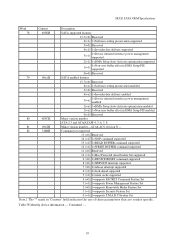
...15-7(=0) Reserved 6(=x) 1=Software setting preservation enabled 5(=0) Reserved 4(=x) 1=In-order data delivery enabled 3(=x) 1=Device initiated interface power management enabled 2(=x) 1=DMA Setup Auto-Activate optimization enabled 1(=x) 1=Non-zero buffer ...ATA/ATAPI-4, 5, 6, 7, 8 81 0042H Minor version number-ATA8-ACS revision 3f -- 82 746BH Command set supported 15 (=0) Reserved 14 (=1) 1=NOP command supported 13 (=1) 1=READ BUFFER command supported 12 (=1) 1=WRITE BUFFER command supported 11 (=0) Reserved 10 (=1) 1=Host Protected Area Feature Set supported 9 (=0) 1=DEVICE...
...15-7(=0) Reserved 6(=x) 1=Software setting preservation enabled 5(=0) Reserved 4(=x) 1=In-order data delivery enabled 3(=x) 1=Device initiated interface power management enabled 2(=x) 1=DMA Setup Auto-Activate optimization enabled 1(=x) 1=Non-zero buffer ...ATA/ATAPI-4, 5, 6, 7, 8 81 0042H Minor version number-ATA8-ACS revision 3f -- 82 746BH Command set supported 15 (=0) Reserved 14 (=1) 1=NOP command supported 13 (=1) 1=READ BUFFER command supported 12 (=1) 1=WRITE BUFFER command supported 11 (=0) Reserved 10 (=1) 1=Host Protected Area Feature Set supported 9 (=0) 1=DEVICE...

Specifications
Page 137
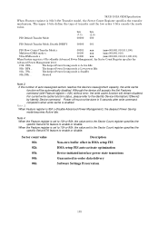
... default. Command 11101111 Command Block Input Registers Register 76543210 Data -------- Device -------- Error ...See Below... LBA High -------- After power on defaults Note 1. 137 ABT will be set 90H Disable use of Serial ATA feature 55H Disable read look-ahead feature 66H Disable reverting to power...Power Management 06H Enable Power-Up in Standby feature set 07H Power-Up in Standby feature set device spin-up 10H Enable use of Serial ATA feature AAH Enable read look-ahead feature CCH Enable reverting to power on reset, the...
... default. Command 11101111 Command Block Input Registers Register 76543210 Data -------- Device -------- Error ...See Below... LBA High -------- After power on defaults Note 1. 137 ABT will be set 90H Disable use of Serial ATA feature 55H Disable read look-ahead feature 66H Disable reverting to power...Power Management 06H Enable Power-Up in Standby feature set 07H Power-Up in Standby feature set device spin-up 10H Enable use of Serial ATA feature AAH Enable read look-ahead feature CCH Enable reverting to power on reset, the...
Specifications
Page 138
... 80h - Power off must not be automatically disabled. Note 4. The upper 5 bits define the type of auto reassigned sectors reaches the device's reassignment capacity, the write cache function will remain disabled. The deepest Power Saving mode is set to 10h or 90h, the value set... to the Sector Count register specifies the specific Serial ATA feature to enable or disable. FEh ... For current write cache function status, please refer to the Identify Device Information(129word) by Identify Device command. If the number of transfer and the low order 3 bits ...
... 80h - Power off must not be automatically disabled. Note 4. The upper 5 bits define the type of auto reassigned sectors reaches the device's reassignment capacity, the write cache function will remain disabled. The deepest Power Saving mode is set to 10h or 90h, the value set... to the Sector Count register specifies the specific Serial ATA feature to enable or disable. FEh ... For current write cache function status, please refer to the Identify Device Information(129word) by Identify Device command. If the number of transfer and the low order 3 bits ...

Specifications
Page 147
... Selective self-test routine When the value in the Self-test execution status byte and ATA registers as below and executes command completion. When all three test spans have been scanned, the device shall then set the flag to enable off -line scan is interrupted by the Extended...in the S.M.A.R.T. In this case, the user shall set the offline scan pending and active flags in captive mode Off-line mode: The device executes command completion before executing the specified routine. When the test spans defined have been scanned. 5K320 SATA OEM Specification 131 Reserved 132 ...
... Selective self-test routine When the value in the Self-test execution status byte and ATA registers as below and executes command completion. When all three test spans have been scanned, the device shall then set the flag to enable off -line scan is interrupted by the Extended...in the S.M.A.R.T. In this case, the user shall set the offline scan pending and active flags in captive mode Off-line mode: The device executes command completion before executing the specified routine. When the test spans defined have been scanned. 5K320 SATA OEM Specification 131 Reserved 132 ...

Specifications
Page 150
... data collection activity Current segment pointer Off-line data collection capability S.M.A.R.T. Any other non-zero value written by the host into the device's Sector Count register before issuing this subcommand shall cause the automatic Off-line data collection feature to be set to be enabled. ...D4h) even if the automatic off -line data collection activities which version of F8h written by the device. All multi-byte fields shown in these data structures follow the ATA/ATAPI-6 specification for byte ordering, namely that make up the Attribute Value information. This data structure ...
... data collection activity Current segment pointer Off-line data collection capability S.M.A.R.T. Any other non-zero value written by the host into the device's Sector Count register before issuing this subcommand shall cause the automatic Off-line data collection feature to be set to be enabled. ...D4h) even if the automatic off -line data collection activities which version of F8h written by the device. All multi-byte fields shown in these data structures follow the ATA/ATAPI-6 specification for byte ordering, namely that make up the Attribute Value information. This data structure ...

Specifications
Page 154
... 5K320 SATA OEM Specification These bytes are the minimum time in minutes to the entries in its entirety using the S.M.A.R.T. Filled with 00h Table 115 Device Attribute Thresholds Data Structure Offset 2 00h 12 02h .. .. 12 15Eh 18 16Ah 131 17Ch 1 1FFh 512 Format binary (*1) (*1) Value 0010h (*2)...-byte fields shown in these data structures follow the ATA/ATAPI-6 specification for each Threshold entry in the field. The sequence of the first 511 bytes in the data structure. 14.40.3 Device Attribute Thresholds Data Structure The following defines the 512 bytes...
... 5K320 SATA OEM Specification These bytes are the minimum time in minutes to the entries in its entirety using the S.M.A.R.T. Filled with 00h Table 115 Device Attribute Thresholds Data Structure Offset 2 00h 12 02h .. .. 12 15Eh 18 16Ah 131 17Ch 1 1FFh 512 Format binary (*1) (*1) Value 0010h (*2)...-byte fields shown in these data structures follow the ATA/ATAPI-6 specification for each Threshold entry in the field. The sequence of the first 511 bytes in the data structure. 14.40.3 Device Attribute Thresholds Data Structure The following defines the 512 bytes...

