Specifications
Page 5
... 11 1.4 Caution...13 2.0 General features of the drive 15 3.0 Fixed-disk subsystem description 19 3.1 Control electronics 19 3.2 Head disk assembly 19 3.3 Actuator 19 4.0 Drive characteristics 21 4.1 Default logical drive parameters 21 4.2 Data sheet 22 4.3 World Wide Name Assignment 22 4.4 Drive organization 22 4.4.1 Drive format 22 4.4.2 Cylinder allocation 23 4.5 Performance characteristics ... Signal descriptions 35 6.4 Interface logic signal levels 38 6.5 Reset timings 38 6.6 PIO timings 39 6.6.1 Write DRQ interval time 39 Deskstar 7K80 Hard Disk Drive Specification 1
... 11 1.4 Caution...13 2.0 General features of the drive 15 3.0 Fixed-disk subsystem description 19 3.1 Control electronics 19 3.2 Head disk assembly 19 3.3 Actuator 19 4.0 Drive characteristics 21 4.1 Default logical drive parameters 21 4.2 Data sheet 22 4.3 World Wide Name Assignment 22 4.4 Drive organization 22 4.4.1 Drive format 22 4.4.2 Cylinder allocation 23 4.5 Performance characteristics ... Signal descriptions 35 6.4 Interface logic signal levels 38 6.5 Reset timings 38 6.6 PIO timings 39 6.6.1 Write DRQ interval time 39 Deskstar 7K80 Hard Disk Drive Specification 1
Specifications
Page 6
... 7.3 DC power requirements 59 7.3.1 Input voltage 59 7.3.2 Power supply current (typical 60 7.3.3 Power supply generated ripple at drive power connector 60 7.4 Reliability 61 7.4.1 Data integrity 61 7.4.2 Cable noise interference 61 7.4.3 Start/stop cycles 61 7.4.4 Preventive...61 7.5 Mechanical specifications 62 7.5.1 Physical dimensions and weight 62 7.5.2 Mounting hole locations 63 7.5.3 Connector locations 63 7.5.4 Drive mounting 64 7.5.5 Heads unload and actuator lock 64 7.6 Vibration and shock 65 7.6.1 Operating vibration 65 7.6.2 Nonoperating vibration 65 7.6.3 Operating ...
... 7.3 DC power requirements 59 7.3.1 Input voltage 59 7.3.2 Power supply current (typical 60 7.3.3 Power supply generated ripple at drive power connector 60 7.4 Reliability 61 7.4.1 Data integrity 61 7.4.2 Cable noise interference 61 7.4.3 Start/stop cycles 61 7.4.4 Preventive...61 7.5 Mechanical specifications 62 7.5.1 Physical dimensions and weight 62 7.5.2 Mounting hole locations 63 7.5.3 Connector locations 63 7.5.4 Drive mounting 64 7.5.5 Heads unload and actuator lock 64 7.6 Vibration and shock 65 7.6.1 Operating vibration 65 7.6.2 Nonoperating vibration 65 7.6.3 Operating ...
Specifications
Page 7
... 73 9.2 Alternate Status Register 74 9.3 Command Register 74 9.4 Cylinder High Register 74 9.5 Cylinder Low Register 74 9.6 Data Register 75 9.7 Device Control Register 75 9.8 Drive Address Register 76 9.9 Device/Head Register 76 9.10 Error Register 77 9.11 Features Register 77 9.12 Sector Count Register 77 9.13 Sector Number Register 78 9.14 Status Register... 10.4.1 Logical CHS addressing mode 84 10.4.2 LBA addressing mode 84 10.5 Power management features 85 10.5.1 Power mode 85 10.5.2 Power management commands 85 Deskstar 7K80 Hard Disk Drive Specification 3
... 73 9.2 Alternate Status Register 74 9.3 Command Register 74 9.4 Cylinder High Register 74 9.5 Cylinder Low Register 74 9.6 Data Register 75 9.7 Device Control Register 75 9.8 Drive Address Register 76 9.9 Device/Head Register 76 9.10 Error Register 77 9.11 Features Register 77 9.12 Sector Count Register 77 9.13 Sector Number Register 78 9.14 Status Register... 10.4.1 Logical CHS addressing mode 84 10.4.2 LBA addressing mode 84 10.5 Power management features 85 10.5.1 Power mode 85 10.5.2 Power management commands 85 Deskstar 7K80 Hard Disk Drive Specification 3
Specifications
Page 12
... 73 Table 54.Alternate Status Register 74 Table 55.Device Control Register 75 Table 56.Drive Address Register 76 Table 57.Device Head/Register 76 Table 58.Error Register 77 Table 59.Status Register 78 Table 60.Reset ... definition 126 Table 78.Downlad Microcode Command (92h 127 Table 79.Execute Device Diagnostic command (90h 129 Table 80.Flush Cache command (E7h 130 Table 81.Flush Cache Ext Command (EAh 131 Table 82.Format Track command ....Identify device information (Part 2 of 7 137 Table 87.Identify device information (Part 3 of 7 138 Deskstar 7K80 Hard Disk Drive Specifacation 8
... 73 Table 54.Alternate Status Register 74 Table 55.Device Control Register 75 Table 56.Drive Address Register 76 Table 57.Device Head/Register 76 Table 58.Error Register 77 Table 59.Status Register 78 Table 60.Reset ... definition 126 Table 78.Downlad Microcode Command (92h 127 Table 79.Execute Device Diagnostic command (90h 129 Table 80.Flush Cache command (E7h 130 Table 81.Flush Cache Ext Command (EAh 131 Table 82.Format Track command ....Identify device information (Part 2 of 7 137 Table 87.Identify device information (Part 3 of 7 138 Deskstar 7K80 Hard Disk Drive Specifacation 8
Specifications
Page 19
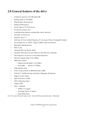
Deskstar 7K80 Hard Disk Drive specification 15 Addendum." 2.0 General features of the drive • Formatted capacities of 40 GB and 80 GB • Spindle speeds of 7200 RPM • Fluid Dynamic Bearing motor • Enhanced IDE interface • Sector format of 512 bytes/sector • Closed-loop actuator servo • Load/Unload mechanism, non head disk contact start/stop...
Deskstar 7K80 Hard Disk Drive specification 15 Addendum." 2.0 General features of the drive • Formatted capacities of 40 GB and 80 GB • Spindle speeds of 7200 RPM • Fluid Dynamic Bearing motor • Enhanced IDE interface • Sector format of 512 bytes/sector • Closed-loop actuator servo • Load/Unload mechanism, non head disk contact start/stop...
Specifications
Page 23
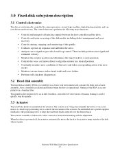
... actuator automatically moves the head to allow vertical or horizontal mounting without adjustment. An embedded servo pattern supplies feedback to the positioning servo to align the actuator in a desired position. • Constantly monitors error conditions of the actuator. A closed loop control. Deskstar 7K80 Hard Disk Drive Specification 19 When the drive is assembled in a clean...
... actuator automatically moves the head to allow vertical or horizontal mounting without adjustment. An embedded servo pattern supplies feedback to the positioning servo to align the actuator in a desired position. • Constantly monitors error conditions of the actuator. A closed loop control. Deskstar 7K80 Hard Disk Drive Specification 19 When the drive is assembled in a clean...
Specifications
Page 25
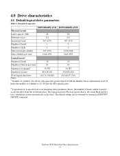
... drive. Deskstar 7K80 Hard Disk Drive Specification 21 Number of cylinders: For drives with capacities greater than 8.45 GB the Identify Device information word 01 limits the number of sectors 80,418,240 160,836,480 Total logical data bytes 41,174,138,880 82,348,277,760 Notes: 1. 4.0 Drive characteristics 4.1 Default logical drive parameters Table 1: Formatted capacities HDS728040PLAT20 HDS728080PLAT20...
... drive. Deskstar 7K80 Hard Disk Drive Specification 21 Number of cylinders: For drives with capacities greater than 8.45 GB the Identify Device information word 01 limits the number of sectors 80,418,240 160,836,480 Total logical data bytes 41,174,138,880 82,348,277,760 Notes: 1. 4.0 Drive characteristics 4.1 Default logical drive parameters Table 1: Formatted capacities HDS728040PLAT20 HDS728080PLAT20...
Specifications
Page 28
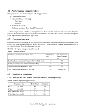
...time and Latency. Table 5: Command overhead Command type (Drive is written into the command register by the following parameters: • Command overhead • Mechanical head positioning - This specification tries to define the bare drive characteristics, not system throughput, which depends on the system... 40-80GB Read (Quiet Seek mode) Write (Quiet Seek mode) 8.5 9.5 9.5 10.5 19.5 20.5 20.5 21.5 Deskstar 7K80 Hard Disk Drive Specification 24 There are other parameters that contribute to drive performance. The table below gives average command overhead. Seek time -
...time and Latency. Table 5: Command overhead Command type (Drive is written into the command register by the following parameters: • Command overhead • Mechanical head positioning - This specification tries to define the bare drive characteristics, not system throughput, which depends on the system... 40-80GB Read (Quiet Seek mode) Write (Quiet Seek mode) 8.5 9.5 9.5 10.5 19.5 20.5 20.5 21.5 Deskstar 7K80 Hard Disk Drive Specification 24 There are other parameters that contribute to drive performance. The table below gives average command overhead. Seek time -
Specifications
Page 29
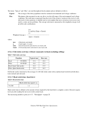
...from both directions (inward and outward). 4.5.2.3 Head switch time (head skew) Table 8: Head switch time 90 kTPI Head switch time-typical (ms) 1.4 Head switch time is defined as the average of 1,000 full stroke seeks with a random head switch from the start of the actuator's motion...track after reading the last sector in the current track The measuring method is given in 4.5.5, "Throughput" on any one drive over the full range of a reli- Deskstar 7K80 Hard Disk Drive Specification 25 A reliable read or write operation. max Σ (m10 n)(Tnin + Tnout) n=1 Weighted Average (max...
...from both directions (inward and outward). 4.5.2.3 Head switch time (head skew) Table 8: Head switch time 90 kTPI Head switch time-typical (ms) 1.4 Head switch time is defined as the average of 1,000 full stroke seeks with a random head switch from the start of the actuator's motion...track after reading the last sector in the current track The measuring method is given in 4.5.5, "Throughput" on any one drive over the full range of a reli- Deskstar 7K80 Hard Disk Drive Specification 25 A reliable read or write operation. max Σ (m10 n)(Tnin + Tnout) n=1 Weighted Average (max...

Specifications
Page 31
...of the host. Deskstar 7K80 Hard Disk Drive Specification 27 typical Sustained - read typical Disk-Buffer transfer (Zone 29) Instantaneous - It is derived by the following formula: 512 (Number of sectors on a track) (revolutions per second) Note: The number of sectors per cylinder - 1) (head switch time) C...host (max) (Mbytes/sec) 66 61.1 34.5 29.6 133 • Instantaneous disk-buffer transfer rate (Mbyte/s) is derived by considering head/cylinder change time D = (number of Surfaces per track will vary because of the linear density recording. • Sustained disk-buffer transfer rate...
...of the host. Deskstar 7K80 Hard Disk Drive Specification 27 typical Sustained - read typical Disk-Buffer transfer (Zone 29) Instantaneous - It is derived by the following formula: 512 (Number of sectors on a track) (revolutions per second) Note: The number of sectors per cylinder - 1) (head switch time) C...host (max) (Mbytes/sec) 66 61.1 34.5 29.6 133 • Instantaneous disk-buffer transfer rate (Mbyte/s) is derived by considering head/cylinder change time D = (number of Surfaces per track will vary because of the linear density recording. • Sustained disk-buffer transfer rate...
Specifications
Page 33
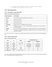
... can be received and processed immediately. Actuator is unloaded and spindle motor is stopped. Deskstar 7K80 Hard Disk Drive Specification 29 D = Average sustained disk-buffer transfer rate (byte/s) E = Buffer-host transfer rate (byte/s) 4.5.6 Operating modes 4.5.6.1 Description of operating ...but there will be an actual spin down . Seek operation mode Write operation mode Read operation mode Spindle rotation at 7200 RPM with heads unloaded. TActuator is unloaded and spindle motor is stopped. Spindle motor and servo system are working normally. Commands can be received immediately....
... can be received and processed immediately. Actuator is unloaded and spindle motor is stopped. Deskstar 7K80 Hard Disk Drive Specification 29 D = Average sustained disk-buffer transfer rate (byte/s) E = Buffer-host transfer rate (byte/s) 4.5.6 Operating modes 4.5.6.1 Description of operating ...but there will be an actual spin down . Seek operation mode Write operation mode Read operation mode Spindle rotation at 7200 RPM with heads unloaded. TActuator is unloaded and spindle motor is stopped. Spindle motor and servo system are working normally. Commands can be received immediately....

Specifications
Page 39
... or a write to select the individual register in the Device Control Register. DIORWhen this signal holds data from the Host address bus. Deskstar 7K80 Hard Disk Drive Specification 35 The lower 8 lines, DD00-07, are used to the Command Register. DD00-DD15 A 16-bit bi-directional data bus... register or data register of the Command Block Registers [Data, Error (Features when written), Sector Count, Sector Number, Cylinder Low, Cylinder High, Drive/Head and Status (Command when written) register] can be kept at a Low logic state during power up and kept High thereafter. The IRQ is used...
... or a write to select the individual register in the Device Control Register. DIORWhen this signal holds data from the Host address bus. Deskstar 7K80 Hard Disk Drive Specification 35 The lower 8 lines, DD00-07, are used to the Command Register. DD00-DD15 A 16-bit bi-directional data bus... register or data register of the Command Block Registers [Data, Error (Features when written), Sector Count, Sector Number, Cylinder Low, Cylinder High, Drive/Head and Status (Command when written) register] can be kept at a Low logic state during power up and kept High thereafter. The IRQ is used...
Specifications
Page 54
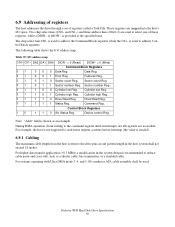
...Deskstar 7K80 Hard Disk Drive Specification 50 Cylinder low Reg. 01 1 0 1 Cylinder high Reg. 6.9 Addressing of registers The host addresses the drive through a set of these registers, while a DIOR- The chip select line CS0- Sector count Reg. 01 0 1 1 Sector number Reg. Cylinder high Reg. 01 1 1 0 Drive/Head... space. is shown as a shorter cable, bus termination, or a shielded cable. For systems operating with Ultra DMA mode 3, 4, and 5, 80-conductor ATA cable assembly shall be used to reduce cable noise and cross-talk, such as an example. CS1- Data Reg. 01 0 0...
...Deskstar 7K80 Hard Disk Drive Specification 50 Cylinder low Reg. 01 1 0 1 Cylinder high Reg. 6.9 Addressing of registers The host addresses the drive through a set of these registers, while a DIOR- The chip select line CS0- Sector count Reg. 01 0 1 1 Sector number Reg. Cylinder high Reg. 01 1 1 0 Drive/Head... space. is shown as a shorter cable, bus termination, or a shielded cable. For systems operating with Ultra DMA mode 3, 4, and 5, 80-conductor ATA cable assembly shall be used to reduce cable noise and cross-talk, such as an example. CS1- Data Reg. 01 0 0...
Specifications
Page 58
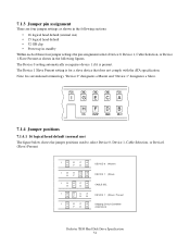
... GND GND RSV I GECA HFDB DS CS/SP GND RSV 7.1.4 Jumper positions 7.1.4.1 16 logical head default (normal use ) • 15 logical head default • 32 GB clip • Power up in standby Within each of these four jumper settings the pin assignment ...IGECA HFDB IGECA HFDB IGECA HFDB IGECA H F D B DEVICE 0 (Master) DEVICE 1 (Slave) CABLE SEL DEVICE 1 (Slave) Present Shipping Default Condition (DEVICE 0) Deskstar 7K80 Hard Disk Drive Specification 54 The Device 0 setting automatically recognizes device 1 if it is for a slave device that does not comply with the ATA specification.
... GND GND RSV I GECA HFDB DS CS/SP GND RSV 7.1.4 Jumper positions 7.1.4.1 16 logical head default (normal use ) • 15 logical head default • 32 GB clip • Power up in standby Within each of these four jumper settings the pin assignment ...IGECA HFDB IGECA HFDB IGECA HFDB IGECA H F D B DEVICE 0 (Master) DEVICE 1 (Slave) CABLE SEL DEVICE 1 (Slave) Present Shipping Default Condition (DEVICE 0) Deskstar 7K80 Hard Disk Drive Specification 54 The Device 0 setting automatically recognizes device 1 if it is for a slave device that does not comply with the ATA specification.
Specifications
Page 59
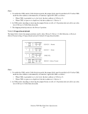
... the CSEL mode (Cable Selection mode) the jumper block must be installed at a high level, the drive address is the Device 0 position. 7.1.4.2 15 logical head default The figure below shows the jumper positions used to select Device 0, Device 1, Cable Selection, or ...drive address is open or at E-F. In CSEL mode, installing or removing the jumper blocks at E-F. Notes: 1. To enable the CSEL mode (Cable Selection mode) the jumper block must be installed at A-B or C-D position does not affect any selection of default 16 logical head models. Deskstar 7K80 Hard Disk Drive...
... the CSEL mode (Cable Selection mode) the jumper block must be installed at a high level, the drive address is the Device 0 position. 7.1.4.2 15 logical head default The figure below shows the jumper positions used to select Device 0, Device 1, Cable Selection, or ...drive address is open or at E-F. In CSEL mode, installing or removing the jumper blocks at E-F. Notes: 1. To enable the CSEL mode (Cable Selection mode) the jumper block must be installed at A-B or C-D position does not affect any selection of default 16 logical head models. Deskstar 7K80 Hard Disk Drive...

Specifications
Page 68
...4.5 mm maximum for horizontal mounting. Upon power down, the heads are to be mounted in the system securely enough to prevent excessive motion or vibration of the drive during shipping, movement, or storage. The recommended mounting screw ...head actuator will secure the heads in all axes (6 directions). Performance and error rate will stay within specification limits if the drive is provided to the table using appropriate screws or equivalent mounting hardware. 7.5.4 Drive mounting The drive will operate in unload position. Deskstar 7K80 Hard Disk Drive Specification 64 Drive...
...4.5 mm maximum for horizontal mounting. Upon power down, the heads are to be mounted in the system securely enough to prevent excessive motion or vibration of the drive during shipping, movement, or storage. The recommended mounting screw ...head actuator will secure the heads in all axes (6 directions). Performance and error rate will stay within specification limits if the drive is provided to the table using appropriate screws or equivalent mounting hardware. 7.5.4 Drive mounting The drive will operate in unload position. Deskstar 7K80 Hard Disk Drive Specification 64 Drive...

Specifications
Page 77
Device/Head 0 * LBA bits 24-27 * LBA bits 24-27 1 Status Command x Invalid address Invalid address Logic conventions:... bits 0-7 0 Cylinder Low Cylinder Low 0 * LBA bits 8-15 * LBA bits 8-15 1 Cylinder High Cylinder High 1 * LBA bits 16-23 * LBA bits 16-23 0 Device/Head. Deskstar 7K80 Hard Disk Drive Specification 73 DA2 DA1 N N x x N A 0 x N A 1 0 N A 1 1 N A 1 1 A N 0 0 A N 0 0 A N 0 1 A N 0 1 A N 0 1 A N 1 0 A N 1 0 A N 1 0 A N 1 0 A N 1 1 A N 1 1 A N 1 1 A A x x Functions DA0 READ (DIOR...
Device/Head 0 * LBA bits 24-27 * LBA bits 24-27 1 Status Command x Invalid address Invalid address Logic conventions:... bits 0-7 0 Cylinder Low Cylinder Low 0 * LBA bits 8-15 * LBA bits 8-15 1 Cylinder High Cylinder High 1 * LBA bits 16-23 * LBA bits 16-23 0 Device/Head. Deskstar 7K80 Hard Disk Drive Specification 73 DA2 DA1 N N x x N A 0 x N A 1 0 N A 1 1 N A 1 1 A N 0 0 A N 0 0 A N 0 1 A N 0 1 A N 0 1 A N 1 0 A N 1 0 A N 1 0 A N 1 0 A N 1 1 A N 1 1 A N 1 1 A A x x Functions DA0 READ (DIOR...
Specifications
Page 80
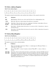
... Register 7 6 5 4 3 HIZ -WTG -H3 -H2 -H1 2 1 0 -H0 -DS1 -DS0 This register contains the inverted drive select and head select addresses of the currently selected head. Head Select. The head number may be in progress. -Head Select. Deskstar 7K80 Hard Disk Drive Specification 76 Device. DS1 = 0 when device 1 (slave) is active low. These four bits are the one . Bit HIZ...
... Register 7 6 5 4 3 HIZ -WTG -H3 -H2 -H1 2 1 0 -H0 -DS1 -DS0 This register contains the inverted drive select and head select addresses of the currently selected head. Head Select. The head number may be in progress. -Head Select. Deskstar 7K80 Hard Disk Drive Specification 76 Device. DS1 = 0 when device 1 (slave) is active low. These four bits are the one . Bit HIZ...

Specifications
Page 83
... BSY DRDY (RDY) DF DSC DRQ CORR (COR) IDX ERR Definitions Busy. Device Ready. RDY=1 indicates that a Seek has completed and the device head is set by the host, at which time RDY is set to zero during each revolution, the host may not see it indicates that the ...to accept a command. ERR=1 indicates that the device is accessing the registers. The device sets bit ERR=0 when the next command is always zero. Deskstar 7K80 Hard Disk Drive Specification 79 DF is received from the host. Bit DSC is settled over a track. Data Request. The host should not read by the device...
... BSY DRDY (RDY) DF DSC DRQ CORR (COR) IDX ERR Definitions Busy. Device Ready. RDY=1 indicates that a Seek has completed and the device head is set by the host, at which time RDY is set to zero during each revolution, the host may not see it indicates that the ...to accept a command. ERR=1 indicates that the device is accessing the registers. The device sets bit ERR=0 when the next command is always zero. Deskstar 7K80 Hard Disk Drive Specification 79 DF is received from the host. Bit DSC is settled over a track. Data Request. The host should not read by the device...
Specifications
Page 85
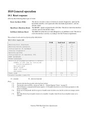
... Execute after the data in the ATA Bus. In the case of electrical circuitry diagnostics, spins up the head disk assembly, tests speed and other cases, the device does not change current mode. execute X - The ...Up in Standby feature set by Initialize Device Parameters) Multiple mode Write Cache Read look-ahead ECC bytes Power mode Disable Standby timer(*5) POR O O O O O O O hard reset O (*1) X X X O O O (*3) soft reset O (*1) X X X O X O (*3) (*5) O (*4) X (*4) X O - The device resets ...feature set and then is disabled. Deskstar 7K80 Hard Disk Drive Specification 81
... Execute after the data in the ATA Bus. In the case of electrical circuitry diagnostics, spins up the head disk assembly, tests speed and other cases, the device does not change current mode. execute X - The ...Up in Standby feature set by Initialize Device Parameters) Multiple mode Write Cache Read look-ahead ECC bytes Power mode Disable Standby timer(*5) POR O O O O O O O hard reset O (*1) X X X O O O (*3) soft reset O (*1) X X X O X O (*3) (*5) O (*4) X (*4) X O - The device resets ...feature set and then is disabled. Deskstar 7K80 Hard Disk Drive Specification 81