
Specifications
Page 5
... location 23 6.1.2 4pin DC Power connector 24 6.1.3 AT signal connector 24 6.2 Signal definitions (PATA model 25 6.3 Signal descriptions 26 6.4 Interface logic signal levels (PATA model 29 6.4.1 Signal definition (SATA model 29 6.4.2 Out of band signaling (SATA model 30 6.5 Signal timings (PATA model 31 6.5.1 Reset timings 31 6.6 PIO timings 32 6.6.1 Write DRQ interval time 32 6.6.2 Read...
... location 23 6.1.2 4pin DC Power connector 24 6.1.3 AT signal connector 24 6.2 Signal definitions (PATA model 25 6.3 Signal descriptions 26 6.4 Interface logic signal levels (PATA model 29 6.4.1 Signal definition (SATA model 29 6.4.2 Out of band signaling (SATA model 30 6.5 Signal timings (PATA model 31 6.5.1 Reset timings 31 6.6 PIO timings 32 6.6.1 Write DRQ interval time 32 6.6.2 Read...

Specifications
Page 6
... 39 6.8.6 Device Pausing Write DMA 40 6.8.7 Device Terminating Write DMA 41 6.8.8 Host Terminating Write DMA 42 6.9 Addressing of registers 43 6.9.1 Cabling 43 7.0 Jumper Settings (PATA model 45 7.1 Connector location 45 7.1.1 Jumper pin identification 45 7.1.2 Jumper pin assignment 46 7.1.3 Jumper positions 46 7.2 Environment 50 7.2.1 Temperature and humidity 50 7.2.2 Corrosion test 51 7.3 DC...
... 39 6.8.6 Device Pausing Write DMA 40 6.8.7 Device Terminating Write DMA 41 6.8.8 Host Terminating Write DMA 42 6.9 Addressing of registers 43 6.9.1 Cabling 43 7.0 Jumper Settings (PATA model 45 7.1 Connector location 45 7.1.1 Jumper pin identification 45 7.1.2 Jumper pin assignment 46 7.1.3 Jumper positions 46 7.2 Environment 50 7.2.1 Temperature and humidity 50 7.2.2 Corrosion test 51 7.3 DC...
Specifications
Page 12
...Mode 96 Table 72. Command Set (subcommand 109 Table 75. Identify Device command (ECh 124 Table 88. Identify device information (Part 1 of PATA model 51 Table 48. Rotational shock 60 Table 55. Alternate Status Register 68 Table 59. Power conditions 80 Table 69. Command Set (1 of 2 ...66. Device Configuration Overlay Features register values 114 Table 79. Flush Cache Ext Command (EAh 121 Table 85. Power supply current of SATA model 52 Table 49. Check Power Mode command (E5h/98h 111 Table 76. Diagnostic codes 76 Table 67. Seek overlap 90 Table 71. ...
...Mode 96 Table 72. Command Set (subcommand 109 Table 75. Identify Device command (ECh 124 Table 88. Identify device information (Part 1 of PATA model 51 Table 48. Rotational shock 60 Table 55. Alternate Status Register 68 Table 59. Power conditions 80 Table 69. Command Set (1 of 2 ...66. Device Configuration Overlay Features register values 114 Table 79. Flush Cache Ext Command (EAh 121 Table 85. Power supply current of SATA model 52 Table 49. Check Power Mode command (E5h/98h 111 Table 76. Diagnostic codes 76 Table 67. Seek overlap 90 Table 71. ...
Specifications
Page 15
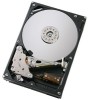
HDS725050KLA360 *Please note default setting is 1.5Gbps. These specifications are subject to Serial ATA 1.0 1.3 Abbreviations Abbreviation A AC AT ATA BIOS C CSA C-UL Cyl DC DFT DMA ... Discharge Federal Communications Commission field replacement unit gravity (a unit of force) Deskstar 7K500 and Deskstar E7K500 Hard Disk Drive specification 1 AT Attachment with the following model numbers: • Deskstar 7K500 - 1.0 General 1.1 Introduction This document describes the specifications of the Deskstar 7K500 and Deskstar E7K500, a 3.5-inch, 7200-rpm hard disk drive with...
HDS725050KLA360 *Please note default setting is 1.5Gbps. These specifications are subject to Serial ATA 1.0 1.3 Abbreviations Abbreviation A AC AT ATA BIOS C CSA C-UL Cyl DC DFT DMA ... Discharge Federal Communications Commission field replacement unit gravity (a unit of force) Deskstar 7K500 and Deskstar E7K500 Hard Disk Drive specification 1 AT Attachment with the following model numbers: • Deskstar 7K500 - 1.0 General 1.1 Introduction This document describes the specifications of the Deskstar 7K500 and Deskstar E7K500, a 3.5-inch, 7200-rpm hard disk drive with...
Specifications
Page 37
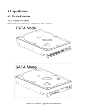
6.0 Specification 6.1 Electrical Interface 6.1.1 Connector location Refer to the following illustration to see the location of the connectors: PATA Model SATA Model Deskstar 7K500 and Deskstar E7K500 Hard Disk Drive Specification 23
6.0 Specification 6.1 Electrical Interface 6.1.1 Connector location Refer to the following illustration to see the location of the connectors: PATA Model SATA Model Deskstar 7K500 and Deskstar E7K500 Hard Disk Drive Specification 23
Specifications
Page 38
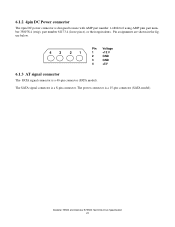
Deskstar 7K500 and Deskstar E7K500 Hard Disk Drive Specification 24 Pin assignments are shown in the figure below. 43 21 Pin Voltage 1 +12 V 2 GND 3 GND 4 +5V 6.1.3 AT signal connector The PATA signal connector is a 8-pin connector. The SATA signal connector is a 40-pin connector (PATA model). The power connector is designed to mate with AMP part number 1-480424-0 using AMP pins part number 350078-4 (strip), part number 61173-4 (loose piece), or their equivalents. 6.1.2 4pin DC Power connector The 4pin DC power connector is a 15-pin connector (SATA model).
Deskstar 7K500 and Deskstar E7K500 Hard Disk Drive Specification 24 Pin assignments are shown in the figure below. 43 21 Pin Voltage 1 +12 V 2 GND 3 GND 4 +5V 6.1.3 AT signal connector The PATA signal connector is a 8-pin connector. The SATA signal connector is a 40-pin connector (PATA model). The power connector is designed to mate with AMP part number 1-480424-0 using AMP pins part number 350078-4 (strip), part number 61173-4 (loose piece), or their equivalents. 6.1.2 4pin DC Power connector The 4pin DC power connector is a 15-pin connector (SATA model).
Specifications
Page 39
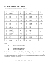
at the moment the host decides to their original definitions upon assertion of the DMACK- 6.2 Signal definitions (PATA model) The pin assignments of interface signals are redefined during the Ultra DMA protocol to provide special functions. I TTL 03 DD7 I/O 3-state 05 DD6 I/O 3-state 07 ...
at the moment the host decides to their original definitions upon assertion of the DMACK- 6.2 Signal definitions (PATA model) The pin assignments of interface signals are redefined during the Ultra DMA protocol to provide special functions. I TTL 03 DD7 I/O 3-state 05 DD6 I/O 3-state 07 ...
Specifications
Page 43
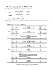
...The corresponding pin to P11 in the power cable receptacle connector shall always be connected to Tx+/ - 6.4 Interface logic signal levels (PATA model) The interface logic signals have the following electrical specifications: Inputs Outputs: Input High Voltage Input Low Voltage Output High Voltage Output Low Voltage 2.0... V min 0.8 V max. 2.4 V min. 0.5 V max. 6.4.1 Signal definition (SATA model) SATA has receivers and drivers to be grounded P12 Gnd 1st mate P13 V12 12V power,pre-chage,2nd mate P14 V12 12V power P15...
...The corresponding pin to P11 in the power cable receptacle connector shall always be connected to Tx+/ - 6.4 Interface logic signal levels (PATA model) The interface logic signals have the following electrical specifications: Inputs Outputs: Input High Voltage Input Low Voltage Output High Voltage Output Low Voltage 2.0... V min 0.8 V max. 2.4 V min. 0.5 V max. 6.4.1 Signal definition (SATA model) SATA has receivers and drivers to be grounded P12 Gnd 1st mate P13 V12 12V power,pre-chage,2nd mate P14 V12 12V power P15...
Specifications
Page 44
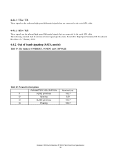
... signals that are connected to the serial ATA cable. Serial ATA: High Speed Serialized AT Attachment Revision 1.0a 7-January, 2003 6.4.2 Out of band signaling (SATA model) Table 19: The timing of COMRESET, COMINT and COMWAKE Table 20: Parameter descriptions PARAMETER DESCRIPTION t1 ALINE primitives t2 Spacing t3 ALIGN primitives t4 Psacing...
... signals that are connected to the serial ATA cable. Serial ATA: High Speed Serialized AT Attachment Revision 1.0a 7-January, 2003 6.4.2 Out of band signaling (SATA model) Table 19: The timing of COMRESET, COMINT and COMWAKE Table 20: Parameter descriptions PARAMETER DESCRIPTION t1 ALINE primitives t2 Spacing t3 ALIGN primitives t4 Psacing...
Specifications
Page 45
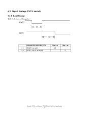
Max (µs) 31 Deskstar 7K500 and Deskstar E7K500 Hard Disk Drive Specification 31 6.5 Signal timings (PATA model) 6.5.1 Reset timings Table 21: System reset timing chart RESETt10 BUSY t14 PARAMETER DESCRIPTION t10 RESET low width t14 RESET high to not BUSY Min (µs) 25 -
Max (µs) 31 Deskstar 7K500 and Deskstar E7K500 Hard Disk Drive Specification 31 6.5 Signal timings (PATA model) 6.5.1 Reset timings Table 21: System reset timing chart RESETt10 BUSY t14 PARAMETER DESCRIPTION t10 RESET low width t14 RESET high to not BUSY Min (µs) 25 -
Specifications
Page 62
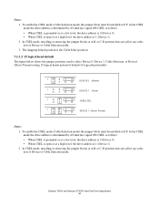
... Drive Specification 48 In CSEL mode, installing or removing the jumper blocks at A-B or C-D position does not affect any selection of default 16 logical head models. IGECA HFDB IGECA HFDB IGECA HFDB IGECA HFDB DEVICE 0 (Master) DEVICE 1 (Slave) CABLE SEL DEVICE 1 (Slave) Present Notes: 1. In CSEL mode, installing or removing the...
... Drive Specification 48 In CSEL mode, installing or removing the jumper blocks at A-B or C-D position does not affect any selection of default 16 logical head models. IGECA HFDB IGECA HFDB IGECA HFDB IGECA HFDB DEVICE 0 (Master) DEVICE 1 (Slave) CABLE SEL DEVICE 1 (Slave) Present Notes: 1. In CSEL mode, installing or removing the...
Specifications
Page 66
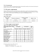
... connected or disconnected to the legacy power connector while power is being applied to the drive (no sign of corrosion inside and outside of PATA model +5 Volts [mA] +12 Volts [mA] Total [W] (values in milliamps. 7.2.2 Corrosion test The drive shows no hot plug/unplug is allowed. ... the drive electronics, power supply voltage spikes must not exceed specifications. 7.3.2 Power supply current (typical) Table 47: Power supply current of PATA model Power supply current of the hard disk assembly and is functional after being subjected to seven days at 40% duty cycle 2 Seek duty = 30...
... connected or disconnected to the legacy power connector while power is being applied to the drive (no sign of corrosion inside and outside of PATA model +5 Volts [mA] +12 Volts [mA] Total [W] (values in milliamps. 7.2.2 Corrosion test The drive shows no hot plug/unplug is allowed. ... the drive electronics, power supply voltage spikes must not exceed specifications. 7.3.2 Power supply current (typical) Table 47: Power supply current of PATA model Power supply current of the hard disk assembly and is functional after being subjected to seven days at 40% duty cycle 2 Seek duty = 30...

Specifications
Page 67
... supply with the performance of the drive, the drive must remain within the above regulation tolerance. Table 48: Power supply current of SATA model Power supply current of SATA model +5 Volts [mA] +12 Volts [mA] (values in a user system frame which has no electrical level difference at drive power connector Maximum (mV...
... supply with the performance of the drive, the drive must remain within the above regulation tolerance. Table 48: Power supply current of SATA model Power supply current of SATA model +5 Volts [mA] +12 Volts [mA] (values in a user system frame which has no electrical level difference at drive power connector Maximum (mV...

Specifications
Page 71
7.5.3 Connector locations 4 REF 4.6+/-0.5 SATA model 42.73 REF 13.43 REF 33.39 (3X) 5.08+/-0.1 Deskstar 7K500 and Deskstar E7K500 Hard Disk Drive Specification 57
7.5.3 Connector locations 4 REF 4.6+/-0.5 SATA model 42.73 REF 13.43 REF 33.39 (3X) 5.08+/-0.1 Deskstar 7K500 and Deskstar E7K500 Hard Disk Drive Specification 57

Specifications
Page 74
... procedures. • No error occurs with a 10 G half-sine shock pulse of 11 ms duration in all models. • No data loss occurs with a 30 G half-sine shock pulse of 4 ms duration in all models. • No data loss occurs with a 55 G half-sine shock pulse of 2 ms duration in all... models. 7.6.4 Nonoperating shock The drive will operate with no degradation of performance after being subjected to shock pulses with...
... procedures. • No error occurs with a 10 G half-sine shock pulse of 11 ms duration in all models. • No data loss occurs with a 30 G half-sine shock pulse of 4 ms duration in all models. • No data loss occurs with a 55 G half-sine shock pulse of 2 ms duration in all... models. 7.6.4 Nonoperating shock The drive will operate with no degradation of performance after being subjected to shock pulses with...
Specifications
Page 76
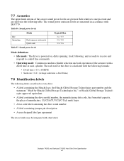
..., unit is ready to receive and respond to every drive: • A label containing the Hitachi logo, the Hitachi Global Storage Technologies part number and the statement " Made by Hitachi Global Storage Technologies Inc." The sound power emission levels are affixed to control line commands. •... are given in Bels relative to one picowatt and are shown in accordance with ISO7779. or Hitachi Global Storage Technologies approved equivalent. • A label containing the drive model number, the manufacturing date code, the formatted capacity, the place of manufacture, UL/CSA/TUV...
..., unit is ready to receive and respond to every drive: • A label containing the Hitachi logo, the Hitachi Global Storage Technologies part number and the statement " Made by Hitachi Global Storage Technologies Inc." The sound power emission levels are affixed to control line commands. •... are given in Bels relative to one picowatt and are shown in accordance with ISO7779. or Hitachi Global Storage Technologies approved equivalent. • A label containing the drive model number, the manufacturing date code, the formatted capacity, the place of manufacture, UL/CSA/TUV...
Specifications
Page 77
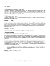
...board. The UL and C-UL recognition mark or the CSA monogram for CSA certification appears on the drive. 7.9.2 German safety mark All models are made of material with a UL recognized flammability rating of its life. The flammability rating is marked or etched on the manufacturing process... meets the requirements of the international treaty on Test Requirement: EN60950:1992+A1-4, but the GS mark is not applicable to the Protocol Hitachi Global Storage Technologies requires the following: • that no packaging used for the shipment of the product use controlled CFCs in the manufacturing...
...board. The UL and C-UL recognition mark or the CSA monogram for CSA certification appears on the drive. 7.9.2 German safety mark All models are made of material with a UL recognized flammability rating of its life. The flammability rating is marked or etched on the manufacturing process... meets the requirements of the international treaty on Test Requirement: EN60950:1992+A1-4, but the GS mark is not applicable to the Protocol Hitachi Global Storage Technologies requires the following: • that no packaging used for the shipment of the product use controlled CFCs in the manufacturing...
Specifications
Page 79
... locked mode. This command does not support 80h as that the device is in the "Addendum for details. The interface unique to ProductNameSATA Serial ATA model is the main interface specification which includes the common host interface to section 10.1, "Reset response" on 23 December 2003 with the following deviations: Check...
... locked mode. This command does not support 80h as that the device is in the "Addendum for details. The interface unique to ProductNameSATA Serial ATA model is the main interface specification which includes the common host interface to section 10.1, "Reset response" on 23 December 2003 with the following deviations: Check...
Specifications
Page 139
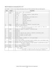
... read Buffer size in 512-byte increments Number of ECC bytes (Vendor unique length is selected via Set Feature Command) Micro code version in ASCII Model number in next to the Content field indicates the use of sectors that are vendor specific. Word 00 01 02 03 04 05 06 07...
... read Buffer size in 512-byte increments Number of ECC bytes (Vendor unique length is selected via Set Feature Command) Micro code version in ASCII Model number in next to the Content field indicates the use of sectors that are vendor specific. Word 00 01 02 03 04 05 06 07...

Specifications
Page 258
... publication to Hitachi Global Storage Technologies products, programs or services do not imply that Hitachi Global Storage Technologies intends to change. Information is true as of the date of Hitachi Global Storage ...only and does not constitute a warranty. Photographs may vary. © Copyright Hitachi Global Storage Technologies Hitachi Global Storage Technologies 5600 Cottle Road San Jose, CA 95193 Produced in the ...make these available in all countries in which Hitachi Global Storage Technologies operates. Other product names are trademarks of their respective companies. Actual ...
... publication to Hitachi Global Storage Technologies products, programs or services do not imply that Hitachi Global Storage Technologies intends to change. Information is true as of the date of Hitachi Global Storage ...only and does not constitute a warranty. Photographs may vary. © Copyright Hitachi Global Storage Technologies Hitachi Global Storage Technologies 5600 Cottle Road San Jose, CA 95193 Produced in the ...make these available in all countries in which Hitachi Global Storage Technologies operates. Other product names are trademarks of their respective companies. Actual ...


