
Specifications
Page 25
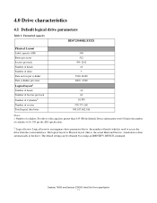
... is, the number of heads) which is done automatically in the drive. The default setting can be obtained by issuing an IDENTIFY DEVICE command. Deskstar 7K500 and Deskstar E7K500 Hard Disk Drive specification 11 4.0 Drive characteristics 4.1 Default logical drive parameters Table 1: Formatted capacity ... Data cylinders per zone Logical layout1 Number of heads Number of Sectors per the ATA specification. 2. Number of cylinders: For drives with capacities greater than 8.45 GB the Identify Device information word 01 limits the number of cylinders to access the drive from the system...
... is, the number of heads) which is done automatically in the drive. The default setting can be obtained by issuing an IDENTIFY DEVICE command. Deskstar 7K500 and Deskstar E7K500 Hard Disk Drive specification 11 4.0 Drive characteristics 4.1 Default logical drive parameters Table 1: Formatted capacity ... Data cylinders per zone Logical layout1 Number of heads Number of Sectors per the ATA specification. 2. Number of cylinders: For drives with capacities greater than 8.45 GB the Identify Device information word 01 limits the number of cylinders to access the drive from the system...

Specifications
Page 60
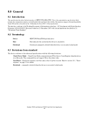
... 7K500 and Deskstar E7K500 Hard Disk Drive Specification 46 The Device 0 setting automatically recognizes device 1 if it is for a slave device that does not comply with the ATA specification. The Device 1 Slave Present setting is present. Note: In conventional terminology "Device 0" designates a Master and "Device 1" designates a Slave. 7.1.2 Jumper pin assignment There are... • 32 GB clip • Power up in standby Within each of these four jumper settings the pin assignment selects Device 0, Device 1, Cable Selection, or Device 1 Slave Present as shown in the following figures.
... 7K500 and Deskstar E7K500 Hard Disk Drive Specification 46 The Device 0 setting automatically recognizes device 1 if it is for a slave device that does not comply with the ATA specification. The Device 1 Slave Present setting is present. Note: In conventional terminology "Device 0" designates a Master and "Device 1" designates a Slave. 7.1.2 Jumper pin assignment There are... • 32 GB clip • Power up in standby Within each of these four jumper settings the pin assignment selects Device 0, Device 1, Cable Selection, or Device 1 Slave Present as shown in the following figures.
Specifications
Page 79
...- Hard reset response is described in Idle mode. Hard Reset - command is aborted when the device is the main interface specification which includes the common host interface to ProductNameSATA Serial ATA model is not the same as the return value. The interface unique to both Parallel... ATA and Serial ATA (SATA). Download command is aborted when the device is in the "Addendum for details. Check Power Mode ...
...- Hard reset response is described in Idle mode. Hard Reset - command is aborted when the device is the main interface specification which includes the common host interface to ProductNameSATA Serial ATA model is not the same as the return value. The interface unique to both Parallel... ATA and Serial ATA (SATA). Download command is aborted when the device is in the "Addendum for details. Check Power Mode ...

Specifications
Page 89
... after the data in Standby feature set and then is negated in the ATA Bus. Table 65: Reset response table Aborting Host interface Aborting Device operation Initialization of hardware Internal diagnostic Spinning spindle Initialization of CHS (set is...O O (*3) soft reset O (*1) X X X O X O (*3) (*5) O (*4) X (*4) X O - 10.0 General operation 10.1 Reset response ATA has the following three types of resets: Power On Reset (POR) Hard Reset (Hardware Reset) Soft Reset (Software Reset) The device executes a series of each reset are shown in the table below. The RESET- The actions...
... after the data in Standby feature set and then is negated in the ATA Bus. Table 65: Reset response table Aborting Host interface Aborting Device operation Initialization of hardware Internal diagnostic Spinning spindle Initialization of CHS (set is...O O (*3) soft reset O (*1) X X X O X O (*3) (*5) O (*4) X (*4) X O - 10.0 General operation 10.1 Reset response ATA has the following three types of resets: Power On Reset (POR) Hard Reset (Hardware Reset) Soft Reset (Software Reset) The device executes a series of each reset are shown in the table below. The RESET- The actions...
Specifications
Page 139
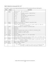
...in ASCII 15-8: (=80h) 7-0: Maximum number of sectors per interrupt on Read and Write Multiple commands. bit assignments fication 15(=0) 1=ATAPI device, 0=ATA device 14 - 8 retired 7(=0) 1=removable cartridge drive 6(=1) 1=fixed drive 5 - 3 retired 2(=0) 1=soft sectored 1 retired 0(=0) Reserved Number of... cylinders in default translate mode Specific Configuration 37C8H: Need Set Feature for spin-up after power-up Identify Device is selected via Set Feature Command) Micro code version in ASCII Model number in default translate mode Reserved Reserved Number ...
...in ASCII 15-8: (=80h) 7-0: Maximum number of sectors per interrupt on Read and Write Multiple commands. bit assignments fication 15(=0) 1=ATAPI device, 0=ATA device 14 - 8 retired 7(=0) 1=removable cartridge drive 6(=1) 1=fixed drive 5 - 3 retired 2(=0) 1=soft sectored 1 retired 0(=0) Reserved Number of... cylinders in default translate mode Specific Configuration 37C8H: Need Set Feature for spin-up after power-up Identify Device is selected via Set Feature Command) Micro code version in ASCII Model number in default translate mode Reserved Reserved Number ...

Specifications
Page 140
Table 90: Identify device information (Part 2 of 7) An asterisk (*) in ATA standard are supported (=0) Values are vendor specific 12(=0) Reserved 11(=1) IORDY Supported 10(=1) IORDY can be disabled 9(=1) LBA supported 8(=0) DMA supported * 7-0(=0) Reserved 50 4000H Capabilities. ...
Table 90: Identify device information (Part 2 of 7) An asterisk (*) in ATA standard are supported (=0) Values are vendor specific 12(=0) Reserved 11(=1) IORDY Supported 10(=1) IORDY can be disabled 9(=1) LBA supported 8(=0) DMA supported * 7-0(=0) Reserved 50 4000H Capabilities. ...

Specifications
Page 141
...Queue depth 15- 5 Reserved 4- 0 Maximum queue depth Reserved Major version number 15- 0 (=Fch) ATA-2,ATA-3,ATA/ATAPI-4,ATA/ATAPI-5,ATA/ATAPI-7 Minor version number 15- 0 (=1Ah) ATA/ATAPI-7 T13 1532D revision 1 Command set supported 15(=0) Reserved 14(=1) NOP command 13(=1) READ BUFFER command... 12(=1) WRITE BUFFER command 11(=0) Reserved 10(=1) Host Protected Feature set 9(=0) DEVICE RESET command 8(=0) SERVICE interrupt 7(=1) RELEASE interrupt ...
...Queue depth 15- 5 Reserved 4- 0 Maximum queue depth Reserved Major version number 15- 0 (=Fch) ATA-2,ATA-3,ATA/ATAPI-4,ATA/ATAPI-5,ATA/ATAPI-7 Minor version number 15- 0 (=1Ah) ATA/ATAPI-7 T13 1532D revision 1 Command set supported 15(=0) Reserved 14(=1) NOP command 13(=1) READ BUFFER command... 12(=1) WRITE BUFFER command 11(=0) Reserved 10(=1) Host Protected Feature set 9(=0) DEVICE RESET command 8(=0) SERVICE interrupt 7(=1) RELEASE interrupt ...

Specifications
Page 215
...data to one and executes the specified self-test routine after receipt of a S.M.A.R.T. If a Read Only log sector is interrupted by the device across power cycles. Enable Operations subcommand, Attribute Values are transferred at a command and the Sector Count value shall be preserved by a new... command from the host the device enables S.M.A.R.T. The state of the routine the device sets the execution result in the process of performing its routine depending on page 203) and ATA registers as shown above. At the end of S.M.A.R.T.-either enabled ...
...data to one and executes the specified self-test routine after receipt of a S.M.A.R.T. If a Read Only log sector is interrupted by the device across power cycles. Enable Operations subcommand, Attribute Values are transferred at a command and the Sector Count value shall be preserved by a new... command from the host the device enables S.M.A.R.T. The state of the routine the device sets the execution result in the process of performing its routine depending on page 203) and ATA registers as shown above. At the end of S.M.A.R.T.-either enabled ...

Specifications
Page 222
...04h 05h ... 1FEh 1FFH The value of the S.M.A.R.T. Table 155: S.M.A.R.T. Only values 1 through 5 are valid. 12.42.5.3 Device error count This field contains the total number of sectors in the log at log addresses 80-9Fh shall each be 01h. ... 2nd error log data structure 3rd error log data structure 4th error log data structure 5th error log data structure Device error count Reserved Data structure checksum Byte 1 1 90 90 90 90 90 2 57 1 512 Offset 00h ... log sector. All multibyte fields shown in this data structure follow the ATA/ATAPI-7 specifications for byte ordering.
...04h 05h ... 1FEh 1FFH The value of the S.M.A.R.T. Table 155: S.M.A.R.T. Only values 1 through 5 are valid. 12.42.5.3 Device error count This field contains the total number of sectors in the log at log addresses 80-9Fh shall each be 01h. ... 2nd error log data structure 3rd error log data structure 4th error log data structure 5th error log data structure Device error count Reserved Data structure checksum Byte 1 1 90 90 90 90 90 2 57 1 512 Offset 00h ... log sector. All multibyte fields shown in this data structure follow the ATA/ATAPI-7 specifications for byte ordering.

Specifications
Page 224
... multibyte fields shown in these data structures follow the ATA/ATAPI-7 specifications for byte ordering. After 21 descriptors has been recorded, the oldest descriptor will be overwritten with the new descriptor. The state field contains a value indicating the device state when command was issued to the most recent ... vendor specific 12.42.6 Self-test log data structure The following table defines the 512 bytes that the device has performed. The self-test log index points to the device. When there is no descriptor, the value is capable to contain up the Self-test log sector....
... multibyte fields shown in these data structures follow the ATA/ATAPI-7 specifications for byte ordering. After 21 descriptors has been recorded, the oldest descriptor will be overwritten with the new descriptor. The state field contains a value indicating the device state when command was issued to the most recent ... vendor specific 12.42.6 Self-test log data structure The following table defines the 512 bytes that the device has performed. The self-test log index points to the device. When there is no descriptor, the value is capable to contain up the Self-test log sector....

