Specifications
Page 13
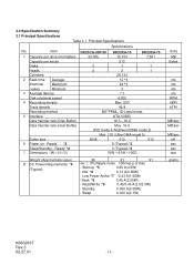
...MB/sec MB/sec MB/sec kB sec sec mm grams K6602637 Rev.3 02.27.01 - 13 - Ready *2 7 DimensionsʢWʷHʷD) DK23CA-30F/30 DK23CA-15 DK23CA-75 30,005 15,103 7,501 512 2 1 1 4 2 1 28,134 12 *1 24 *1 3 7.1 4,200 Max. 530 46.8 ...Power Requirements *4 (Typical) 95 91 91 +5v ʶ 5% Ripple noise 100mvp-p or less - Read/Write *9 0.40/0.40 A(2.0/2.0W) - Standby 0.050 A(0.25W) - Item 1 Capacity per drive (Formatted) Capacity per sector Disks Heads Cylinders 2 Seek time Average (Nominal Maximum value) Minimum 3 Average latency Disk rotational speed...
...MB/sec MB/sec MB/sec kB sec sec mm grams K6602637 Rev.3 02.27.01 - 13 - Ready *2 7 DimensionsʢWʷHʷD) DK23CA-30F/30 DK23CA-15 DK23CA-75 30,005 15,103 7,501 512 2 1 1 4 2 1 28,134 12 *1 24 *1 3 7.1 4,200 Max. 530 46.8 ...Power Requirements *4 (Typical) 95 91 91 +5v ʶ 5% Ripple noise 100mvp-p or less - Read/Write *9 0.40/0.40 A(2.0/2.0W) - Standby 0.050 A(0.25W) - Item 1 Capacity per drive (Formatted) Capacity per sector Disks Heads Cylinders 2 Seek time Average (Nominal Maximum value) Minimum 3 Average latency Disk rotational speed...
Specifications
Page 15
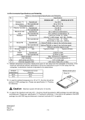
...*1 : Ambient temperature should be measured at a point 10 mm away from the nameplate of the maximum wet bulb 40°C , the drive should be packed in the table below. K6602637 Rev.3 02.27.01 - 15 - Item Specification DK23CA-30F DK23CA-30/15/75 1 Ambient *1 Operational 5 to 55...°C temperature Non-operational -40 to 70°C *2 Temperature gradient Max...
...*1 : Ambient temperature should be measured at a point 10 mm away from the nameplate of the maximum wet bulb 40°C , the drive should be packed in the table below. K6602637 Rev.3 02.27.01 - 15 - Item Specification DK23CA-30F DK23CA-30/15/75 1 Ambient *1 Operational 5 to 55...°C temperature Non-operational -40 to 70°C *2 Temperature gradient Max...
Specifications
Page 27
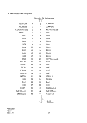
...- 29 INTRQ 31 DA1 33 DA0 35 CS0- 37 DASP- 39 5VDC(Logic) 41 GND(Logic) 43 B JUMPER0 D JUMPER2 F KEY(Removed) 2 GND 4 DD8 6 DD9 8 DD10 10 DD11 12 DD12 14 DD13 16 DD14 18 DD15 20 KEY(Removed) 22 GND 24 GND 26 GND 28 CSEL 30 GND 32 IOCS16- 34...
...- 29 INTRQ 31 DA1 33 DA0 35 CS0- 37 DASP- 39 5VDC(Logic) 41 GND(Logic) 43 B JUMPER0 D JUMPER2 F KEY(Removed) 2 GND 4 DD8 6 DD9 8 DD10 10 DD11 12 DD12 14 DD13 16 DD14 18 DD15 20 KEY(Removed) 22 GND 24 GND 26 GND 28 CSEL 30 GND 32 IOCS16- 34...
Specifications
Page 38
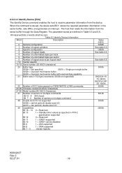
...7 - 0 Vendor Specific Value (HEX.) 045Ah See table 6.6 C837h See table 6.6 See table 6.6 0003h DK23CA-15/ 75: 0400h DK23CA-30F/ 30: 1000h 0004h 8010h 0000h 0B00h K6602637 Rev.3 02.27.01 - 38 - Table 6.5 Identify ...Number of unformatted bytes per sector 6 Number of logical sectors per logical track 7-9 Vendor specific 10-19 Serial number (20 ASCII characters) 20 Buffer type 0000h = Not specified 0001h = ... on READ/WRITE LONG commands 23-26 Firmware revision(8 ASCII Characters) 27-46 Model number(40 ASCII Characters) 47 Number of sectors on multiple commands Bit 15 - 8 80h (fixed)...
...7 - 0 Vendor Specific Value (HEX.) 045Ah See table 6.6 C837h See table 6.6 See table 6.6 0003h DK23CA-15/ 75: 0400h DK23CA-30F/ 30: 1000h 0004h 8010h 0000h 0B00h K6602637 Rev.3 02.27.01 - 38 - Table 6.5 Identify ...Number of unformatted bytes per sector 6 Number of logical sectors per logical track 7-9 Vendor specific 10-19 Serial number (20 ASCII characters) 20 Buffer type 0000h = Not specified 0001h = ... on READ/WRITE LONG commands 23-26 Firmware revision(8 ASCII Characters) 27-46 Model number(40 ASCII Characters) 47 Number of sectors on multiple commands Bit 15 - 8 80h (fixed)...
Specifications
Page 40
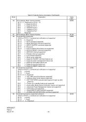
... supported Bit 15 0 = Reserved Bit 14 1 = NOP command supported Bit 13 1 = READ BUFFER command supported Bit 12 1 = WRITE BUFFER command supported Bit 11 0 = Reserved Bit 10 1 = Host Protected Area feature set supported Bit 9 1 = DEVICE RESET command supported Bit 8 1 = SERVICE interrupt supported Bit 7 1 = Release interrupt supported Bit 6 1 = Look-ahead supported Bit 5 1 = Write... set notification not supported Bit 15 0 (fixed) Bit 14 1 (fixed) Bit 13 - 0 0 = Reserved Value (HEX.) 003Eh 0013h 346Bh 4188h 4000h K6602637 Rev.3 02.27.01 - 40 -
... supported Bit 15 0 = Reserved Bit 14 1 = NOP command supported Bit 13 1 = READ BUFFER command supported Bit 12 1 = WRITE BUFFER command supported Bit 11 0 = Reserved Bit 10 1 = Host Protected Area feature set supported Bit 9 1 = DEVICE RESET command supported Bit 8 1 = SERVICE interrupt supported Bit 7 1 = Release interrupt supported Bit 6 1 = Look-ahead supported Bit 5 1 = Write... set notification not supported Bit 15 0 (fixed) Bit 14 1 (fixed) Bit 13 - 0 0 = Reserved Value (HEX.) 003Eh 0013h 346Bh 4188h 4000h K6602637 Rev.3 02.27.01 - 40 -

Specifications
Page 88
... consists of DD0-15(16 bit) or DD0-7(8 bit) SYMBOL Description MIN(ns) t0 Cycle Time 120 t1 Address Valid to Address Valid Hold 10 MAX(ns) 30 40 30 K6602637 Rev.3 02.27.01 - 88 - Setup 25 t2 DIOR-/DIOW- Data Hold 5 t6Z DIOR- Negation (MAX) t9 DIOR-/DIOW- to DIOR... 6-4 PIO Data Transfer Timing(Mode 4) t0 Addr Valid *1 t1 t2 t9 DIOR-/DIOW- Data Setup 20 t6 DIOR- Data Setup 20 t4 DIOW- Data Hold 10 t5 DIOR- Pulse Width 70 t2i DIOR-/DIOW- Data tristate t7 Addr Valid To IOCS16-
... consists of DD0-15(16 bit) or DD0-7(8 bit) SYMBOL Description MIN(ns) t0 Cycle Time 120 t1 Address Valid to Address Valid Hold 10 MAX(ns) 30 40 30 K6602637 Rev.3 02.27.01 - 88 - Setup 25 t2 DIOR-/DIOW- Data Hold 5 t6Z DIOR- Negation (MAX) t9 DIOR-/DIOW- to DIOR... 6-4 PIO Data Transfer Timing(Mode 4) t0 Addr Valid *1 t1 t2 t9 DIOR-/DIOW- Data Setup 20 t6 DIOR- Data Setup 20 t4 DIOW- Data Hold 10 t5 DIOR- Pulse Width 70 t2i DIOR-/DIOW- Data tristate t7 Addr Valid To IOCS16-

