
Specifications
Page 9
.... SMART Enable/Disable Attribute AUTOSAVE [B0h, Sub D2h 107 7.5.47. SMART Execute Off-line Immediate [B0h, Sub D4h 109 7.5.49. Write Log EXT [3Fh]...124 7.5.60. Security Disable Password [F6h 91 7.5.29. Security Freeze Lock [F5h] ...93 7.5.32. Seek [7Xh]...96 7.5.35. Set Multiple Mode [C6h] ...104 7.5.43. SMART Disable Operations...
.... SMART Enable/Disable Attribute AUTOSAVE [B0h, Sub D2h 107 7.5.47. SMART Execute Off-line Immediate [B0h, Sub D4h 109 7.5.49. Write Log EXT [3Fh]...124 7.5.60. Security Disable Password [F6h 91 7.5.29. Security Freeze Lock [F5h] ...93 7.5.32. Seek [7Xh]...96 7.5.35. Set Multiple Mode [C6h] ...104 7.5.43. SMART Disable Operations...
Specifications
Page 11
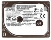
...half-sine wave) [Identify Device Information for Setup] Table 1.1 Identify Device information (Addressing) Product name Word 1 Word 3 Word 6 Word 60 - 61 *1 (Model name) Number of user addressable sectors in LBA mode. *2 : Maximum capacity in a 1.8 type form factor by ... Travelstar C4K60-30 Travelstar C4K60-20 Model name HTC426030G7CE00 HTC426020G7CE10 Capacity (Formatted) 30.005 GB 20.003 GB Height 7.0 mm 7.0 mm Interface ATA-6(IDE) ATA-6(IDE) [Features] - CDR (Constant Density Recording) - Advanced Power Management(APM) - Introduction The Travelstar C4K60-30/20 disk drives...
...half-sine wave) [Identify Device Information for Setup] Table 1.1 Identify Device information (Addressing) Product name Word 1 Word 3 Word 6 Word 60 - 61 *1 (Model name) Number of user addressable sectors in LBA mode. *2 : Maximum capacity in a 1.8 type form factor by ... Travelstar C4K60-30 Travelstar C4K60-20 Model name HTC426030G7CE00 HTC426020G7CE10 Capacity (Formatted) 30.005 GB 20.003 GB Height 7.0 mm 7.0 mm Interface ATA-6(IDE) ATA-6(IDE) [Features] - CDR (Constant Density Recording) - Advanced Power Management(APM) - Introduction The Travelstar C4K60-30/20 disk drives...
Specifications
Page 16
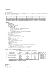
Item Specification Travelstar Travelstar C4K60-30 C4K60-20 Model name HTC426030G7CE00 HTC426020G7CE10 1 Ambient *1 Operational 5 to 60°C temperature Non-operational -40 to 70°C Temperature gradient Max. 20°C /hour 2 Relative humidity Operational 5 to 90 % ... ambient temperature cannot be measured at a point 10 mm away from the nameplate of the maximum wet bulb 40°C , the drive should be measured at point 10 mm away from the nameplate, a substitution method is applied. Environmental Specifications and Reliability Table 3.2 Environmental...
Item Specification Travelstar Travelstar C4K60-30 C4K60-20 Model name HTC426030G7CE00 HTC426020G7CE10 1 Ambient *1 Operational 5 to 60°C temperature Non-operational -40 to 70°C Temperature gradient Max. 20°C /hour 2 Relative humidity Operational 5 to 90 % ... ambient temperature cannot be measured at a point 10 mm away from the nameplate of the maximum wet bulb 40°C , the drive should be measured at point 10 mm away from the nameplate, a substitution method is applied. Environmental Specifications and Reliability Table 3.2 Environmental...

Specifications
Page 17
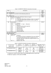
... = 0.4/(average access time + average latency) = 0.4/(average access time + 60/RPM/2) *4 : Caution Data reliability is designed for 24/7 applications. Drive Usage Condition Specifications The drive is not to be measured through 50 ohm resistor. -External Magnetic Field : Within specifications given in Table 3.1 "Principal Specifications" -Drive Grounding : Drive frame should be used for usage under the following...
... = 0.4/(average access time + average latency) = 0.4/(average access time + 60/RPM/2) *4 : Caution Data reliability is designed for 24/7 applications. Drive Usage Condition Specifications The drive is not to be measured through 50 ohm resistor. -External Magnetic Field : Within specifications given in Table 3.1 "Principal Specifications" -Drive Grounding : Drive frame should be used for usage under the following...

Specifications
Page 45
.... After the SET MAX ADDRESS or SET MAX ADDRESS EXT command has been issued, the device reports only the reduced user address space in words 60, 61, 100, 101, 102, and 103. When the 48-bit Address feature set is immediately preceded by a READ NATIVE MAX ADDRESS EXT command. On power...
.... After the SET MAX ADDRESS or SET MAX ADDRESS EXT command has been issued, the device reports only the reduced user address space in words 60, 61, 100, 101, 102, and 103. When the 48-bit Address feature set is immediately preceded by a READ NATIVE MAX ADDRESS EXT command. On power...

Specifications
Page 60
... 6 - 4 0 = Reserved bit 3 1 = Security feature set supported Bit 3 is cleared to select no support for the Host Protected Area feature set. K6610170 Rev.2 Dec 22, 2004 - 60 - bit 7 - 0 Signature Code Bits 7:0 of this word shall contain the value A5h. Table 7.6 DEVICE CONFIGURATION SET command Data Structure(Continued) Word Description 7 Command Set / Feature...
... 6 - 4 0 = Reserved bit 3 1 = Security feature set supported Bit 3 is cleared to select no support for the Host Protected Area feature set. K6610170 Rev.2 Dec 22, 2004 - 60 - bit 7 - 0 Signature Code Bits 7:0 of this word shall contain the value A5h. Table 7.6 DEVICE CONFIGURATION SET command Data Structure(Continued) Word Description 7 Command Set / Feature...

Specifications
Page 66
... bit 15-9 0 = Reserved bit 8 1 = Multiple sector setting is valid bit 7 - 0 Current setting for number of sectors that can be transferred per interrupt on R/W MULTIPLE command 60-61 Total addressable LBA 62 63 64 65 66 67 68 69-74 75 76-79 Obsolete Multi-word DMA transfer bit 15 - 8 Multi-word...
... bit 15-9 0 = Reserved bit 8 1 = Multiple sector setting is valid bit 7 - 0 Current setting for number of sectors that can be transferred per interrupt on R/W MULTIPLE command 60-61 Total addressable LBA 62 63 64 65 66 67 68 69-74 75 76-79 Obsolete Multi-word DMA transfer bit 15 - 8 Multi-word...
Specifications
Page 71
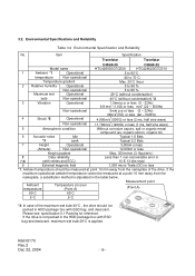
... Number of SPT 16383 *2 (3FFFh) 16383 *2 (3FFFh) 16 (0010h) 16 (0010h) 63 (3Fh) 63 (3Fh) Word 60 - 61 *1 Word 100 - 103 Total LBA 58,605,120 (37E 3E40h) 39,070,080 (254 2980h) *1: Words 60-61 reflect the total number of CYL. K6610170 Rev.2 Dec 22, 2004 - 71 - Word Table 7.8 IDENTIFY DEVICE...
... Number of SPT 16383 *2 (3FFFh) 16383 *2 (3FFFh) 16 (0010h) 16 (0010h) 63 (3Fh) 63 (3Fh) Word 60 - 61 *1 Word 100 - 103 Total LBA 58,605,120 (37E 3E40h) 39,070,080 (254 2980h) *1: Words 60-61 reflect the total number of CYL. K6610170 Rev.2 Dec 22, 2004 - 71 - Word Table 7.8 IDENTIFY DEVICE...

Specifications
Page 99
... *1: Maximum sector number and maximum head number are fixed values, and the values are 16 and 63. After a successful command completion, IDENTIFY DEVICE response Word 60-61 and Word 100-103 reflect the maximum address set with this command.
... *1: Maximum sector number and maximum head number are fixed values, and the values are 16 and 63. After a successful command completion, IDENTIFY DEVICE response Word 60-61 and Word 100-103 reflect the maximum address set with this command.

Specifications
Page 101
... the command block registers is the maximum device size as a SET MAX ADDRESS command. If this command. After a successful command completion, IDENTIFY DEVICE response Word 60-61 and Word 100-103 reflect the maximum address set with this command is immediately preceded by a READ MAX ADDRESS command, it is interpreted as...
... the command block registers is the maximum device size as a SET MAX ADDRESS command. If this command. After a successful command completion, IDENTIFY DEVICE response Word 60-61 and Word 100-103 reflect the maximum address set with this command is immediately preceded by a READ MAX ADDRESS command, it is interpreted as...

Specifications
Page 114
... (Cylinder High) register when the Command register was written. Table 7.31 Error Log Data Structure Byte n ~ n+11 n+12 ~ n+23 n+24 ~ n+35 n+36 ~ n+47 n+48 ~ n+59 n+60 ~ n+89 First command data structure Second command data structure Third command data structure Fourth command data structure Fifth command data structure Error data structure Description...
... (Cylinder High) register when the Command register was written. Table 7.31 Error Log Data Structure Byte n ~ n+11 n+12 ~ n+23 n+24 ~ n+35 n+36 ~ n+47 n+48 ~ n+59 n+60 ~ n+89 First command data structure Second command data structure Third command data structure Fourth command data structure Fifth command data structure Error data structure Description...

Specifications
Page 125
... LBA address bit 27-24 01h XX The WRITE LONG command is changed by Features Register = 44h, 68 bytes of ECC will be 8-bits wide. 7.5.60.
... LBA address bit 27-24 01h XX The WRITE LONG command is changed by Features Register = 44h, 68 bytes of ECC will be 8-bits wide. 7.5.60.

Specifications
Page 135
DMARQ (device) DMACK(host) STOP (host) Figure 8.6 Host pausing an Ultra DMA Read tRP HDMARDY(host) tRFS DSTROBE (device) DD(15:0) (device) Note: The host asserts STOP to -pause time K6610170 Rev.2 Dec 22, 2004 - 135 - SYMBOL tRFS tRP Mode 0(ns) Mode 1(ns) Mode 2(ns) Mode3(ns) MIN MAX MIN MAX MIN MAX MIN MAX 75 70 60 60 160 125 100 100 Mode4(ns) MIN MAX 60 100 Mode5(ns) Description MIN MAX 50 Ready-to-final STROBE time 85 Ready-to request termination of the Ultra DMA burst no sooner than tRP after HDMARDYis negated.
DMARQ (device) DMACK(host) STOP (host) Figure 8.6 Host pausing an Ultra DMA Read tRP HDMARDY(host) tRFS DSTROBE (device) DD(15:0) (device) Note: The host asserts STOP to -pause time K6610170 Rev.2 Dec 22, 2004 - 135 - SYMBOL tRFS tRP Mode 0(ns) Mode 1(ns) Mode 2(ns) Mode3(ns) MIN MAX MIN MAX MIN MAX MIN MAX 75 70 60 60 160 125 100 100 Mode4(ns) MIN MAX 60 100 Mode5(ns) Description MIN MAX 50 Ready-to-final STROBE time 85 Ready-to request termination of the Ultra DMA burst no sooner than tRP after HDMARDYis negated.

Specifications
Page 137
... LI tLI tACK tACK tIO R D Y Z D D (1 5 :0 ) tCVS CRC tCVH tACK DA0, DA1, DA2, CS0-, CS1- Note: The definitions for output drivers turning on tRFS 75 70 60 60 60 50 Ready-to-final-STROBE time tRP 160 125 100 100 100 85 Ready-to release tZAH 20 20 20 20 20 20 Minimum delay...
... LI tLI tACK tACK tIO R D Y Z D D (1 5 :0 ) tCVS CRC tCVH tACK DA0, DA1, DA2, CS0-, CS1- Note: The definitions for output drivers turning on tRFS 75 70 60 60 60 50 Ready-to-final-STROBE time tRP 160 125 100 100 100 85 Ready-to release tZAH 20 20 20 20 20 20 Minimum delay...

Specifications
Page 140
is negated. SYMBOL tRFS tRP Mode 0(ns) Mode 1(ns) Mode 2(ns) MIN MAX MIN MAX MIN MAX 75 70 60 160 125 100 Mode 3(ns) MIN MAX 60 100 Mode 4(ns) Mde5(ns) Description MIN MAX MIN MAX 60 50 Ready-to-final STROBE time 100 85 Ready-to request termination of the Ultra DMA burst no sooner than tRP after DDMARDY- Figure 8.11 Device pausing an Ultra DMA Write tRP DMARQ (device) DMACK(host) STOP (host) DDMARDY(device) tRFS HSTROBE (host) DD(15:0) (host) Note: The device negates DMARQ to -pause time K6610170 Rev.2 Dec 22, 2004 - 140 -
is negated. SYMBOL tRFS tRP Mode 0(ns) Mode 1(ns) Mode 2(ns) MIN MAX MIN MAX MIN MAX 75 70 60 160 125 100 Mode 3(ns) MIN MAX 60 100 Mode 4(ns) Mde5(ns) Description MIN MAX MIN MAX 60 50 Ready-to-final STROBE time 100 85 Ready-to request termination of the Ultra DMA burst no sooner than tRP after DDMARDY- Figure 8.11 Device pausing an Ultra DMA Write tRP DMARQ (device) DMACK(host) STOP (host) DDMARDY(device) tRFS HSTROBE (host) DD(15:0) (host) Note: The device negates DMARQ to -pause time K6610170 Rev.2 Dec 22, 2004 - 140 -

Specifications
Page 142
... sender tLI 0 150 0 150 0 150 0 100 0 100 0 75 Limited interlock time tMLI 20 20 20 20 20 20 Interlock time with minimum tRFS 75 70 60 60 60 50 Ready-to-final- Note: The definitions for DMACK_ K6610170 Rev.2 Dec 22, 2004 - 142 - Mode 0(ns) Mode 1(ns) Mode 2(ns) Mode 3(ns) Mode 4(ns...
... sender tLI 0 150 0 150 0 150 0 100 0 100 0 75 Limited interlock time tMLI 20 20 20 20 20 20 Interlock time with minimum tRFS 75 70 60 60 60 50 Ready-to-final- Note: The definitions for DMACK_ K6610170 Rev.2 Dec 22, 2004 - 142 - Mode 0(ns) Mode 1(ns) Mode 2(ns) Mode 3(ns) Mode 4(ns...