Specifications
Page 1
All rights reserved. Read and recommend drive usage cautions to your end user. Keep this manual with care. (Total 144 pages) H I T A C H I ©2004, Hitachi Global Storage Technologies. K6610170 Rev.2 Dec 22, 2004 - 1 - OEM Manual Hard Disk Drive Specifications Travelstar C4K60-30/20 REV.2 Models: HTC426030G7CE00 HTC426020G7CE10 Caution for Safety Read Safety descriptions carefully.
All rights reserved. Read and recommend drive usage cautions to your end user. Keep this manual with care. (Total 144 pages) H I T A C H I ©2004, Hitachi Global Storage Technologies. K6610170 Rev.2 Dec 22, 2004 - 1 - OEM Manual Hard Disk Drive Specifications Travelstar C4K60-30/20 REV.2 Models: HTC426030G7CE00 HTC426020G7CE10 Caution for Safety Read Safety descriptions carefully.
Specifications
Page 3
... 5.1, Page 24 Sec. 5.2, Page 25 K6610170 Rev.2 Dec 22, 2004 - 3 - To use this product safely This manual is for drive usage in this manual. To use this product. - Safety caution in this manual Followings are not followed. Power Supply Requirements - Keep this manual... consists a word of this product. (Caution before attempting to use the product, read the caution for the original purchaser of Travelstar C4K60-30/20 and intendes to the neighboring property ,if safety instructions are indicated as follows: Caution: This symbol indicates that your end users read...
... 5.1, Page 24 Sec. 5.2, Page 25 K6610170 Rev.2 Dec 22, 2004 - 3 - To use this product safely This manual is for drive usage in this manual. To use this product. - Safety caution in this manual Followings are not followed. Power Supply Requirements - Keep this manual... consists a word of this product. (Caution before attempting to use the product, read the caution for the original purchaser of Travelstar C4K60-30/20 and intendes to the neighboring property ,if safety instructions are indicated as follows: Caution: This symbol indicates that your end users read...

Specifications
Page 6
... from time to time in the event of such revisions or changes. Hitachi does not perform data recovery. 21. Hitachi makes no representations or warranties with respect to notify any damage. (Keep some extra packages for the drive transportation) 20. Further Hitachi reserves the right to revise this publication and to make changes from any...
... from time to time in the event of such revisions or changes. Hitachi does not perform data recovery. 21. Hitachi makes no representations or warranties with respect to notify any damage. (Keep some extra packages for the drive transportation) 20. Further Hitachi reserves the right to revise this publication and to make changes from any...

Specifications
Page 7
...LBA Mid Register (Cylinder Low Register 33 7.1.7. Command Register ...35 K6610170 Rev.2 Dec 22, 2004 - 7 - Mounting HDD ...20 4.2.1. Attention for HDD Installation ...22 4.3. Power Interface...26 6.2. Error register ...32 7.1.3. LBA High Register (Cylinder High Register 33...Off Sequence...18 4.0 Installation ...19 4.1. Single HDD Test Condition ...21 4.2.3. Features Register...32 7.1.4. Drive Usage Condition Specifications 17 3.4. Mounting HDD with screws ...20 4.2.2. Description of the Interface Signals 29 7.0 Logical Interface ...31 7.1. Sector Count Register ...32 ...
...LBA Mid Register (Cylinder Low Register 33 7.1.7. Command Register ...35 K6610170 Rev.2 Dec 22, 2004 - 7 - Mounting HDD ...20 4.2.1. Attention for HDD Installation ...22 4.3. Power Interface...26 6.2. Error register ...32 7.1.3. LBA High Register (Cylinder High Register 33...Off Sequence...18 4.0 Installation ...19 4.1. Single HDD Test Condition ...21 4.2.3. Features Register...32 7.1.4. Drive Usage Condition Specifications 17 3.4. Mounting HDD with screws ...20 4.2.2. Description of the Interface Signals 29 7.0 Logical Interface ...31 7.1. Sector Count Register ...32 ...

Specifications
Page 8
... 7.2.1. 48-bit Addressing Feature Set...36 7.2.2. Security Mode Feature ...41 7.2.5. Idle [97h, E3h] ...72 7.5.12. Read DMA [C8h, C9h]...75 7.5.16. Read Multiple [C4h]...84 7.5.20. Command Protocol ...50 7.3.1. Non-Data Command ...51 7.3.5. Check Power Mode [98h, E5h]...55 7.5.2. Format Track [50h] (Vendor Specific 64 7.5.10. Device Configuration Freeze Lock [B1h...
... 7.2.1. 48-bit Addressing Feature Set...36 7.2.2. Security Mode Feature ...41 7.2.5. Idle [97h, E3h] ...72 7.5.12. Read DMA [C8h, C9h]...75 7.5.16. Read Multiple [C4h]...84 7.5.20. Command Protocol ...50 7.3.1. Non-Data Command ...51 7.3.5. Check Power Mode [98h, E5h]...55 7.5.2. Format Track [50h] (Vendor Specific 64 7.5.10. Device Configuration Freeze Lock [B1h...
Specifications
Page 11
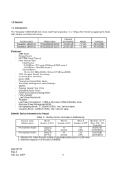
...Head - ME2PRML Read Channel - Low Power Consumption: 0.25W at Idle mode, 0.08W at Standby mode - Introduction The Travelstar C4K60-30/20 disk drives reach high capacities in CHS mode is 8,455MB. Data Transfer Rate (Host-Device) -16.6 MB/sec: PIO mode-4/Multiword... number of CYL. On-the-fly ECC Correction - K6610170 Rev.2 Dec 22, 2004 - 11 - Product name Travelstar C4K60-30 Travelstar C4K60-20 Model name HTC426030G7CE00 HTC426020G7CE10 Capacity (Formatted) 30.005 GB 20.003 GB Height 7.0 mm 7.0 mm Interface ATA-6(IDE) ATA-6(IDE) [Features] - Buffer: 2MB - Non-...
...Head - ME2PRML Read Channel - Low Power Consumption: 0.25W at Idle mode, 0.08W at Standby mode - Introduction The Travelstar C4K60-30/20 disk drives reach high capacities in CHS mode is 8,455MB. Data Transfer Rate (Host-Device) -16.6 MB/sec: PIO mode-4/Multiword... number of CYL. On-the-fly ECC Correction - K6610170 Rev.2 Dec 22, 2004 - 11 - Product name Travelstar C4K60-30 Travelstar C4K60-20 Model name HTC426030G7CE00 HTC426020G7CE10 Capacity (Formatted) 30.005 GB 20.003 GB Height 7.0 mm 7.0 mm Interface ATA-6(IDE) ATA-6(IDE) [Features] - Buffer: 2MB - Non-...
Specifications
Page 13
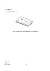
2.0 Components Travelstar C4K60-30/20 Disk Drive Figure 2.1 Overview of Travelstar C4K60-30/20 (7.0mm height) K6610170 Rev.2 Dec 22, 2004 - 13 -
2.0 Components Travelstar C4K60-30/20 Disk Drive Figure 2.1 Overview of Travelstar C4K60-30/20 (7.0mm height) K6610170 Rev.2 Dec 22, 2004 - 13 -
Specifications
Page 14
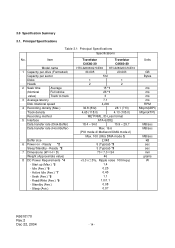
... drive (Formatted) Capacity per sector Disks Heads 2 Seek time Average (Nominal Full stroke value) Track to track 3 Average latency Disk rotational speed 4 Recording density (Max.) Track density Recording method 5 Interface Data transfer rate (Disk-Buffer) Data transfer rate (Host-Buffer) Buffer size 6 Power on - Sleep (Ave.) Travelstar Travelstar C4K60-30 C4K60-20 HTC426030G7CE00 HTC426020G7CE10 30.005 20...
... drive (Formatted) Capacity per sector Disks Heads 2 Seek time Average (Nominal Full stroke value) Track to track 3 Average latency Disk rotational speed 4 Recording density (Max.) Track density Recording method 5 Interface Data transfer rate (Disk-Buffer) Data transfer rate (Host-Buffer) Buffer size 6 Power on - Sleep (Ave.) Travelstar Travelstar C4K60-30 C4K60-20 HTC426030G7CE00 HTC426020G7CE10 30.005 20...
Specifications
Page 16
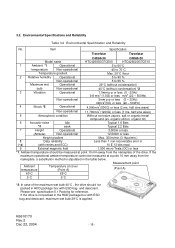
...;C 5°C 5°C *2: In case of the maximum wet bulb 40°C , the drive should be measured at a point 10 mm away from the nameplate of the drive. If the drive is not packed in the table below. Item Specification Travelstar Travelstar C4K60-30 C4K60-20 Model name HTC426030G7CE00 HTC426020G7CE10 1 Ambient *1 Operational 5 to 60°C temperature Non-operational -40...
...;C 5°C 5°C *2: In case of the maximum wet bulb 40°C , the drive should be measured at a point 10 mm away from the nameplate of the drive. If the drive is not packed in the table below. Item Specification Travelstar Travelstar C4K60-30 C4K60-20 Model name HTC426030G7CE00 HTC426020G7CE10 1 Ambient *1 Operational 5 to 60°C temperature Non-operational -40...

Specifications
Page 17
...and regular torque. -Physical/Electrical Interface: ATA-6 -Handling : Do not add Electrical Static Discharge, and Vibration and Shock to the drive. Continuous motor spinning should be measured through 50 ohm resistor. -External Magnetic Field : Within specifications given in Table 3.2 -Mounting :.... Clicking noise of continuous POH condition, the transition to be taken in Table 3.1 "Principal Specifications" -Drive Grounding : Drive frame should be less than 20% of side mounting holes) should be grounded to 48 hours period. Seek rate for 24/7 applications. ...
...and regular torque. -Physical/Electrical Interface: ATA-6 -Handling : Do not add Electrical Static Discharge, and Vibration and Shock to the drive. Continuous motor spinning should be measured through 50 ohm resistor. -External Magnetic Field : Within specifications given in Table 3.2 -Mounting :.... Clicking noise of continuous POH condition, the transition to be taken in Table 3.1 "Principal Specifications" -Drive Grounding : Drive frame should be less than 20% of side mounting holes) should be grounded to 48 hours period. Seek rate for 24/7 applications. ...

Specifications
Page 18
... by the following BIOS sequence is required by the software control after power off the drive Above sequence is a mechanism to maximum 600,000 times during Idle mode. Since normal unload can not be set to maximum 20,000 times during HDD life. Sleep Note: Such as explained in Sec. 3.4.2. 3.4.2. Sleep Also...
... by the following BIOS sequence is required by the software control after power off the drive Above sequence is a mechanism to maximum 600,000 times during Idle mode. Since normal unload can not be set to maximum 20,000 times during HDD life. Sleep Note: Such as explained in Sec. 3.4.2. 3.4.2. Sleep Also...
Specifications
Page 19
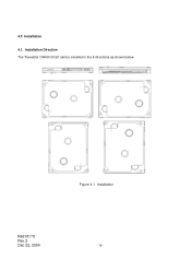
Figure 4.1 Installation K6610170 Rev.2 Dec 22, 2004 - 19 - Installation Direction The Travelstar C4K60-30/20 can be installed in the 6 directions as shown below. 4.0 Installation 4.1.
Figure 4.1 Installation K6610170 Rev.2 Dec 22, 2004 - 19 - Installation Direction The Travelstar C4K60-30/20 can be installed in the 6 directions as shown below. 4.0 Installation 4.1.

Specifications
Page 20
... HDD when mounting. 4.2. Using 4 screws holes, secure the HDD. (b) Use screws with the general electronic equipment. K6610170 Rev.2 Dec 22, 2004 Figure 4.2 Mounting the HDD - 20 -
... HDD when mounting. 4.2. Using 4 screws holes, secure the HDD. (b) Use screws with the general electronic equipment. K6610170 Rev.2 Dec 22, 2004 Figure 4.2 Mounting the HDD - 20 -

Specifications
Page 28
... Table 6.1 Connector pin assignment pin signal name 11 DD4 12 DD11 13 DD3 14 DD12 15 DD2 16 DD13 17 DD1 18 DD14 19 DD0 20 DD15 pin signal name 21 GROUND 22 DMARQ 23 GROUND 24 DIOW25 DIOR26 GROUND 27 IORDY 28 GROUND 29 DMACK30 INTRQ pin signal name 31... on FPC contact is recquired to apply excessive force on shock. 6.2.3. Please secure appropriate margin in the FPC length not to avoid Sn whisker completely. (3) 20.5 +/- 0.05mm width, 0.3 +/- 0.05mm thickness FPC with reinforcement is recommended. (4) 2-layer FPC(one layer is GND plane) is recommended for better signal integrity. (5) Durability ...
... Table 6.1 Connector pin assignment pin signal name 11 DD4 12 DD11 13 DD3 14 DD12 15 DD2 16 DD13 17 DD1 18 DD14 19 DD0 20 DD15 pin signal name 21 GROUND 22 DMARQ 23 GROUND 24 DIOW25 DIOR26 GROUND 27 IORDY 28 GROUND 29 DMACK30 INTRQ pin signal name 31... on FPC contact is recquired to apply excessive force on shock. 6.2.3. Please secure appropriate margin in the FPC length not to avoid Sn whisker completely. (3) 20.5 +/- 0.05mm width, 0.3 +/- 0.05mm thickness FPC with reinforcement is recommended. (4) 2-layer FPC(one layer is GND plane) is recommended for better signal integrity. (5) Durability ...

Specifications
Page 29
... the pin numbers are used for register access other than data register. Table 6.2 shows signal definitions. Table 6.2 Signal List Signal name Pin RESET- 3 DD0-DD15 5-20 DIOW- 24 STOP *1 DIOR- 25 I/O type I I/O I I /O type represents an input signal from the device and "O" represents an output signal from DD(15:0) into the device...
... the pin numbers are used for register access other than data register. Table 6.2 shows signal definitions. Table 6.2 Signal List Signal name Pin RESET- 3 DD0-DD15 5-20 DIOW- 24 STOP *1 DIOR- 25 I/O type I I/O I I /O type represents an input signal from the device and "O" represents an output signal from DD(15:0) into the device...

Specifications
Page 65
... 1 Number of logical cylinders 2 Specific configuration 3 Number of logical heads 4 - 5 Retired 6 Number of logical sectors per logical track 7-9 Vendor Specific 10-19 Serial Number (20 ASCII characters) 20 Retired 21 Retired 22 Number of ECC bytes passed on READ/WRITE LONG commands 23-26 Firmware Revision (8 ASCII Characters) 27-46 Model number...
... 1 Number of logical cylinders 2 Specific configuration 3 Number of logical heads 4 - 5 Retired 6 Number of logical sectors per logical track 7-9 Vendor Specific 10-19 Serial Number (20 ASCII characters) 20 Retired 21 Retired 22 Number of ECC bytes passed on READ/WRITE LONG commands 23-26 Firmware Revision (8 ASCII Characters) 27-46 Model number...

Specifications
Page 72
Idle [97h, E3h] Task File Registers Command LBA High LBA Mid LBA Low Device/Head Sector Count Features 7 6 5 4 3 2 1 0 97h or E3h XX XX XX X X X DRV X X X X Standby Timer Value XX The IDLE command causes the device to enter to the Active Idle Mode. The Sector Count Register sets the standby timer value. Sector Count Value SC = 0 0 7.5.11. By the power on default, the Standby timer is disabled.
Idle [97h, E3h] Task File Registers Command LBA High LBA Mid LBA Low Device/Head Sector Count Features 7 6 5 4 3 2 1 0 97h or E3h XX XX XX X X X DRV X X X X Standby Timer Value XX The IDLE command causes the device to enter to the Active Idle Mode. The Sector Count Register sets the standby timer value. Sector Count Value SC = 0 0 7.5.11. By the power on default, the Standby timer is disabled.

Specifications
Page 85
... number of the block that contained the error. All other errors cause the command to stop after transfer of blocks or the block count) requested. 7.5.20.
... number of the block that contained the error. All other errors cause the command to stop after transfer of blocks or the block count) requested. 7.5.20.

Specifications
Page 91
... XX XX X X X DRV X X X X XX XX The RECALIBRATE command performs no operation. Then the device checks the transferred password. K6610170 Rev.2 Dec 22, 2004 - 91 - Table 7.20 Password Data Format Word Contents 0 Control Word bit 15-1 Reserved bit 0 Identifier 0 = Compare user password, 1 = Compare master password 1-16 Password (32bytes) 17-255 Reserved Device...
... XX XX X X X DRV X X X X XX XX The RECALIBRATE command performs no operation. Then the device checks the transferred password. K6610170 Rev.2 Dec 22, 2004 - 91 - Table 7.20 Password Data Format Word Contents 0 Control Word bit 15-1 Reserved bit 0 Identifier 0 = Compare user password, 1 = Compare master password 1-16 Password (32bytes) 17-255 Reserved Device...

Specifications
Page 93
..., the command executes and the device remains in Locked Mode. The device returns Aborted command error if the device is shown below. - HTC426020G7CE10 27 minutes 20 minutes 7.5.31. Commands disabled by power-off or hardware reset. If the device receives a SECURITY ERASE UNIT command without an immediately prior SECURITY ERASE PREPARE...
..., the command executes and the device remains in Locked Mode. The device returns Aborted command error if the device is shown below. - HTC426020G7CE10 27 minutes 20 minutes 7.5.31. Commands disabled by power-off or hardware reset. If the device receives a SECURITY ERASE UNIT command without an immediately prior SECURITY ERASE PREPARE...