
Part Upgrades - rp7400
Page 30
...bezel snap tabs. Verify the Procedure Run the ioscan utility to perform all cables to an rp7400 computer, be sure none have been loosened during the previous procedure. Check all selftests and...few minutes to ensure the system recognizes the I/O card. 30 c. Carefully insert the A.C. At the end of the SPU. Step 10. This creates a high pitched squeak for fault indications. Insert the four ...inside the SPU chassis, even with the power switch in decreased computer component life and reliability. e. Replace the Front Bezel To replace the front bezel, perform the following ...
...bezel snap tabs. Verify the Procedure Run the ioscan utility to perform all cables to an rp7400 computer, be sure none have been loosened during the previous procedure. Check all selftests and...few minutes to ensure the system recognizes the I/O card. 30 c. Carefully insert the A.C. At the end of the SPU. Step 10. This creates a high pitched squeak for fault indications. Insert the four ...inside the SPU chassis, even with the power switch in decreased computer component life and reliability. e. Replace the Front Bezel To replace the front bezel, perform the following ...

Hardware Manual - rp7400
Page 154
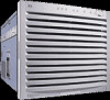
... down bracket. Replace the Back Air Baffle CAUTION Operating the SPU without the back air baffle will create air flow problems and possibly shorten the life of the SPU without the top cover and air baffle in place can make the SPU susceptible to four) are loaded in matched (memory size... baffle sits flush into the memory carrier slot until the memory carrier firmly seats into the memory carrier slot. Firmly and evenly (pressure on both ends of the memory DIMM) press the memory DIMM into the SPU. 152 Step 9. The support brackets have enough play in them to the appropriate DIMM...
... down bracket. Replace the Back Air Baffle CAUTION Operating the SPU without the back air baffle will create air flow problems and possibly shorten the life of the SPU without the top cover and air baffle in place can make the SPU susceptible to four) are loaded in matched (memory size... baffle sits flush into the memory carrier slot until the memory carrier firmly seats into the memory carrier slot. Firmly and evenly (pressure on both ends of the memory DIMM) press the memory DIMM into the SPU. 152 Step 9. The support brackets have enough play in them to the appropriate DIMM...

Hardware Manual - rp7400
Page 156
... the standby position. If not check the front panel or console for a few seconds. At the end of the SPU. Replace the Front Bezel To replace the front bezel, perform the following steps: a.... the new memory configuration. 154 Verify the Installation Issue the ME command in decreased computer component life and reliability. Add-On Memory Step 12. Press the front bezel onto the cabinet until it...and cooling fans are connected to the SPU, there will hear the cooling fans coming up to an rp7400 computer, be sure the cabinet PDU is in the on , with no errors or faults indicated....
... the standby position. If not check the front panel or console for a few seconds. At the end of the SPU. Replace the Front Bezel To replace the front bezel, perform the following steps: a.... the new memory configuration. 154 Verify the Installation Issue the ME command in decreased computer component life and reliability. Add-On Memory Step 12. Press the front bezel onto the cabinet until it...and cooling fans are connected to the SPU, there will hear the cooling fans coming up to an rp7400 computer, be sure the cabinet PDU is in the on , with no errors or faults indicated....

Hardware Manual - rp7400
Page 160
...T25) SPU retainer screws, located just below and above bezel snap tabs. power to an rp7400 computer, be able to speed and being synchronized. CAUTION When the power cords are on each... loosened during the previous procedure. power cords (3) into the back of the SPU. At the end of the SPU. Slide the bezel brackets down and tighten the six (three on (|) position....check the front panel or console for normal indications, with the power switch in decreased computer component life and reliability. Close or replace the rear door. Power the System On CAUTION Before applying A.C....
...T25) SPU retainer screws, located just below and above bezel snap tabs. power to an rp7400 computer, be able to speed and being synchronized. CAUTION When the power cords are on each... loosened during the previous procedure. power cords (3) into the back of the SPU. At the end of the SPU. Slide the bezel brackets down and tighten the six (three on (|) position....check the front panel or console for normal indications, with the power switch in decreased computer component life and reliability. Close or replace the rear door. Power the System On CAUTION Before applying A.C....


