Maintenance and Service Guide
Page 3
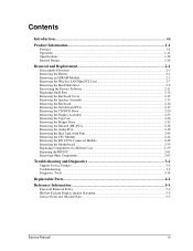
...11 Replacing Small Parts ...2-12 Removing the Keyboard Cover...2-13 Removing the Speaker Assembly ...2-15 Removing the Keyboard ...2-16 Removing the Switchboard PCA ...2-19 Removing the CD/DVD Drive...2-20 Removing the Display Assembly...2-23 Removing the Top Case ...2-26 Removing the Floppy Drive...2-32... Removing the Infrared (I/R) PCA...2-36 Removing the Audio PCA ...2-38 Removing the Heat Sink (with Fan 2-40 Removing the CPU Module ...2-44 Removing the RJ11/1394 Connector Module...
...11 Replacing Small Parts ...2-12 Removing the Keyboard Cover...2-13 Removing the Speaker Assembly ...2-15 Removing the Keyboard ...2-16 Removing the Switchboard PCA ...2-19 Removing the CD/DVD Drive...2-20 Removing the Display Assembly...2-23 Removing the Top Case ...2-26 Removing the Floppy Drive...2-32... Removing the Infrared (I/R) PCA...2-36 Removing the Audio PCA ...2-38 Removing the Heat Sink (with Fan 2-40 Removing the CPU Module ...2-44 Removing the RJ11/1394 Connector Module...
Maintenance and Service Guide
Page 4
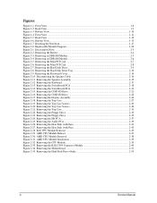
...PCI Card 2-8 Figure 2-7. Removing the Hard Disk Drive Tray 2-10 Figure 2-9. Removing the Speaker Assembly 2-15 Figure 2-12. Removing the Switchboard PCA 2-18 Figure 2-14. Removing the Display Assembly 2-24 Figure 2-18. Removing the Top Case...2-27 Figure 2-19. Removing the Floppy Drive ... 2-39 Figure 2-32 Removing the CPU Module 2-39 Figure 2-33. Figures Figure 1-1. Bottom View...1-13 Figure 1-7. Resetting the Notebook ...1-17 Figure 1-8. Replaceable Module Diagram 1-24 Figure 2-1. Removing the Mini PCI Card 2-7 Figure 2-6. Disconnecting the Speaker Cable 2-14 Figure ...
...PCI Card 2-8 Figure 2-7. Removing the Hard Disk Drive Tray 2-10 Figure 2-9. Removing the Speaker Assembly 2-15 Figure 2-12. Removing the Switchboard PCA 2-18 Figure 2-14. Removing the Display Assembly 2-24 Figure 2-18. Removing the Top Case...2-27 Figure 2-19. Removing the Floppy Drive ... 2-39 Figure 2-32 Removing the CPU Module 2-39 Figure 2-33. Figures Figure 1-1. Bottom View...1-13 Figure 1-7. Resetting the Notebook ...1-17 Figure 1-8. Replaceable Module Diagram 1-24 Figure 2-1. Removing the Mini PCI Card 2-7 Figure 2-6. Disconnecting the Speaker Cable 2-14 Figure ...
Maintenance and Service Guide
Page 30
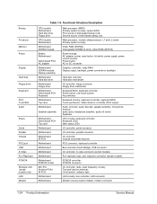
... Motherboard SDRAM module Display assembly Motherboard Hard disk drive Motherboard Floppy drive Motherboard Switchboard PCA Keyboard Motherboard Top case Motherboard Speaker assembly Motherboard Switchboard PCA Top case Motherboard Motherboard Motherboard IR PCA Motherboard Motherboard Motherboard Motherboard Motherboard PCMCIA socket Mini PCI Antenna PCAs IR PCA Motherboard Motherboard Main processor (MMO) Primary system circuitry, system BIOS First source...
... Motherboard SDRAM module Display assembly Motherboard Hard disk drive Motherboard Floppy drive Motherboard Switchboard PCA Keyboard Motherboard Top case Motherboard Speaker assembly Motherboard Switchboard PCA Top case Motherboard Motherboard Motherboard IR PCA Motherboard Motherboard Motherboard Motherboard Motherboard PCMCIA socket Mini PCI Antenna PCAs IR PCA Motherboard Motherboard Main processor (MMO) Primary system circuitry, system BIOS First source...
Maintenance and Service Guide
Page 45
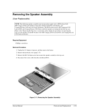
... then remove the battery. 2. Figure 2-11. Remove the keyboard cover (page 2-13). 3. The HP Pavilion ze5x00, HP Compaq nx9010 and nx9008, and Compaq Presario 2500 Series notebook speakers are integrated into the top case. Disconnect the 4-wire cable from the switchboard PCA. Remove the M2.5×6.0mm screw that secures the speaker assembly to the "Removing...
... then remove the battery. 2. Figure 2-11. Remove the keyboard cover (page 2-13). 3. The HP Pavilion ze5x00, HP Compaq nx9010 and nx9008, and Compaq Presario 2500 Series notebook speakers are integrated into the top case. Disconnect the 4-wire cable from the switchboard PCA. Remove the M2.5×6.0mm screw that secures the speaker assembly to the "Removing...
Maintenance and Service Guide
Page 46
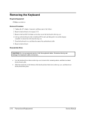
... 1. Lift up on the bottom of its normal position, and then reconnect the keyboard cable. • Slide the metal tabs on the keyboard at the switchboard PCA end, and then pull it toward the display assembly to the top case. 4. Excessive flexing can damage the keyboard cable connectors. • Lay the keyboard...
... 1. Lift up on the bottom of its normal position, and then reconnect the keyboard cable. • Slide the metal tabs on the keyboard at the switchboard PCA end, and then pull it toward the display assembly to the top case. 4. Excessive flexing can damage the keyboard cable connectors. • Lay the keyboard...
Maintenance and Service Guide
Page 48
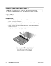
... cover (page 2-13). 3. Removing the Switchboard PCA NOTE: This section applies only to HP Pavilion 4x00, HP Compaq nx9005 and nx9000, Compaq Evo Notebook N1050v and N1010v, and Compaq Presario 2100 and 1100 models. Unplug the AC adapter, if present, and then remove the battery. 2. Removing the Switchboard PCA HP Pavilion 4x00, HP Compaq nx9005 and nx9000, Compaq Evo...
... cover (page 2-13). 3. Removing the Switchboard PCA NOTE: This section applies only to HP Pavilion 4x00, HP Compaq nx9005 and nx9000, Compaq Evo Notebook N1050v and N1010v, and Compaq Presario 2100 and 1100 models. Unplug the AC adapter, if present, and then remove the battery. 2. Removing the Switchboard PCA HP Pavilion 4x00, HP Compaq nx9005 and nx9000, Compaq Evo...
Maintenance and Service Guide
Page 49
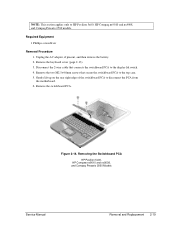
Remove the two M2.5×4.0mm screws that connects the switchboard PCA to the top case. 5. Remove the switchboard PCA. NOTE: This section applies only to disconnect the PCA from the motherboard. 6. Removing the Switchboard PCA HP Pavilion 5x00, HP Compaw nx9010 and nx9008, and Compaq Presario 2500 Models Service Manual Removal and Replacement 2-19 Required Equipment 1 Phillips screwdriver Removal Procedure...
Remove the two M2.5×4.0mm screws that connects the switchboard PCA to the top case. 5. Remove the switchboard PCA. NOTE: This section applies only to disconnect the PCA from the motherboard. 6. Removing the Switchboard PCA HP Pavilion 5x00, HP Compaw nx9010 and nx9008, and Compaq Presario 2500 Models Service Manual Removal and Replacement 2-19 Required Equipment 1 Phillips screwdriver Removal Procedure...
Maintenance and Service Guide
Page 54
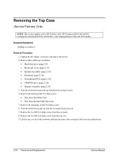
... (page 2-13) • Speaker assembly (page 2-23) • Keyboard (page 2-16) • Switchboard PCA (page 2-19) • CD/DVD drive (page 2-20) • Display assembly (page 2-23) 3. Lift the top case off of the notebook and then disconnect the touch pad cable from the top case. 9. Required Equipment 1 Phillips screwdriver... Remove the remaining 14 M2.5×6.0mm screws. 6. Removing the Top Case (Service Partners Only) NOTE: This section applies only to HP Pavilion 4x00, HP Compaq nx9005 and nx9000, Compaq Evo Notebook N1050v and N1010v, and Compaq Presario 2100 and 1100 models.
... (page 2-13) • Speaker assembly (page 2-23) • Keyboard (page 2-16) • Switchboard PCA (page 2-19) • CD/DVD drive (page 2-20) • Display assembly (page 2-23) 3. Lift the top case off of the notebook and then disconnect the touch pad cable from the top case. 9. Required Equipment 1 Phillips screwdriver... Remove the remaining 14 M2.5×6.0mm screws. 6. Removing the Top Case (Service Partners Only) NOTE: This section applies only to HP Pavilion 4x00, HP Compaq nx9005 and nx9000, Compaq Evo Notebook N1050v and N1010v, and Compaq Presario 2100 and 1100 models.
Maintenance and Service Guide
Page 56
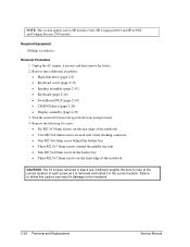
... caution can result in the correct location. Turn the notebook bottom side up with the front facing forward. 4. Remove these additional assemblies: • Hard disk drive (page 2-9) • Keyboard cover (page 2-13) • Speaker assembly (page 2-15) • Keyboard (page 2-16) • Switchboard PCA (page 2-19) • CD/DVD drive (page 2-20) •... battery bay • Three M2.5×7.0mm screws on the front edge of each screw as it is removed and install it in damage to HP Pavilion 5x00, HP Compaq nx9010 and HP nx9008, and Compaq Presario 2500 models.
... caution can result in the correct location. Turn the notebook bottom side up with the front facing forward. 4. Remove these additional assemblies: • Hard disk drive (page 2-9) • Keyboard cover (page 2-13) • Speaker assembly (page 2-15) • Keyboard (page 2-16) • Switchboard PCA (page 2-19) • CD/DVD drive (page 2-20) •... battery bay • Three M2.5×7.0mm screws on the front edge of each screw as it is removed and install it in damage to HP Pavilion 5x00, HP Compaq nx9010 and HP nx9008, and Compaq Presario 2500 models.
Maintenance and Service Guide
Page 59
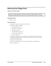
...6. Remove these additional assemblies: • Hard disk drive (page 2-9) • Keyboard cover (page 2-13) • Keyboard (page 2-16) • Switchboard PCA (page 2-19) • Display assembly (page 2-23) • Top case (page 2-26) 3. Unplug the AC adapter, if present, and remove the... side) are missing. Removing the Floppy Drive (Service Partners Only) NOTE: This section applies only to HP Pavilion ze4x00, HP Compaq nx9005 and nx9000, Compaq Evo Notebook N1050v and N1010v, and Compaq Presario 2100 and 1100 models. Required Equipment 1 Phillips screwdriver Removal Procedure ...
...6. Remove these additional assemblies: • Hard disk drive (page 2-9) • Keyboard cover (page 2-13) • Keyboard (page 2-16) • Switchboard PCA (page 2-19) • Display assembly (page 2-23) • Top case (page 2-26) 3. Unplug the AC adapter, if present, and remove the... side) are missing. Removing the Floppy Drive (Service Partners Only) NOTE: This section applies only to HP Pavilion ze4x00, HP Compaq nx9005 and nx9000, Compaq Evo Notebook N1050v and N1010v, and Compaq Presario 2100 and 1100 models. Required Equipment 1 Phillips screwdriver Removal Procedure ...
Maintenance and Service Guide
Page 61
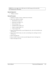
... 2-31 Remove the floppy drive bezel. Remove these additional assemblies: • Hard disk drive (page 2-9) • Keyboard cover (page 2-13) • Keyboard (page 2-16) • Switchboard PCA (page 2-19) • Display assembly (page 2-23) • Top case (page 2-26) 3. Remove the insulating tape that secure the floppy drive and floppy drive bezel... to the TouchPad bracket on the top case. 4. Remove the floppy drive. 6. Remove the M2.0×3.0mm screw that secures the floppy drive bezel to HP Pavilion 5x00, HP Compaq nx9010 and nx9008, and Compaq Presario 2500 models.
... 2-31 Remove the floppy drive bezel. Remove these additional assemblies: • Hard disk drive (page 2-9) • Keyboard cover (page 2-13) • Keyboard (page 2-16) • Switchboard PCA (page 2-19) • Display assembly (page 2-23) • Top case (page 2-26) 3. Remove the insulating tape that secure the floppy drive and floppy drive bezel... to the TouchPad bracket on the top case. 4. Remove the floppy drive. 6. Remove the M2.0×3.0mm screw that secures the floppy drive bezel to HP Pavilion 5x00, HP Compaq nx9010 and nx9008, and Compaq Presario 2500 models.
Maintenance and Service Guide
Page 63
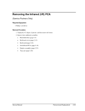
Unplug the AC adapter, if present, and then remove the battery. 2. Remove these additional assemblies: • Hard disk drive (page 2-9) • Keyboard cover (page 2-13) • Keyboard (page 2-16) • Switchboard PCA (page 2-19) • Display assembly (page 2-23) • Top case (page 2-26) Service Manual Removal and Replacement 2-33 Removing the Infrared (I/R) PCA (Service Partners Only) Required Equipment 1 Phillips screwdriver Removal Procedure 1.
Unplug the AC adapter, if present, and then remove the battery. 2. Remove these additional assemblies: • Hard disk drive (page 2-9) • Keyboard cover (page 2-13) • Keyboard (page 2-16) • Switchboard PCA (page 2-19) • Display assembly (page 2-23) • Top case (page 2-26) Service Manual Removal and Replacement 2-33 Removing the Infrared (I/R) PCA (Service Partners Only) Required Equipment 1 Phillips screwdriver Removal Procedure 1.
Maintenance and Service Guide
Page 65
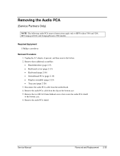
... case. 5. Remove these additional assemblies: • Hard disk drive (page 2-9) • Keyboard cover (page 2-13) • Keyboard (page 2-16) • Switchboard PCA (page 2-19) • Display assembly (page 2-23) • Top case (page 2-26) 3. Unplug the AC adapter, if present, and then remove the ...battery. 2. Remove the audio PCA cable from the motherboard. 4. Remove the two M2.0×3.0mm flathead screws that secure the audio PCA shield to HP Pavilion 5300 and 5200, HP Compaq nx9010, and Compaq Presario 2500 models.
... case. 5. Remove these additional assemblies: • Hard disk drive (page 2-9) • Keyboard cover (page 2-13) • Keyboard (page 2-16) • Switchboard PCA (page 2-19) • Display assembly (page 2-23) • Top case (page 2-26) 3. Unplug the AC adapter, if present, and then remove the ...battery. 2. Remove the audio PCA cable from the motherboard. 4. Remove the two M2.0×3.0mm flathead screws that secure the audio PCA shield to HP Pavilion 5300 and 5200, HP Compaq nx9010, and Compaq Presario 2500 models.
Maintenance and Service Guide
Page 67
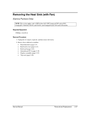
...; Keyboard (page 2-16) • Switchboard PCA (page 2-19) • Display assembly (page 2-23) • Top case (page 2-26) Service Manual Removal and Replacement 2-37 Removing the Heat Sink (with Fan) (Service Partners Only) NOTE: This section applies only to HP Pavilion 4x00, HP Compaq nx9005 and nx9000, Compaq Evo Notebook N1050v and N1010v, and Compaq...
...; Keyboard (page 2-16) • Switchboard PCA (page 2-19) • Display assembly (page 2-23) • Top case (page 2-26) Service Manual Removal and Replacement 2-37 Removing the Heat Sink (with Fan) (Service Partners Only) NOTE: This section applies only to HP Pavilion 4x00, HP Compaq nx9005 and nx9000, Compaq Evo Notebook N1050v and N1010v, and Compaq...
Maintenance and Service Guide
Page 69
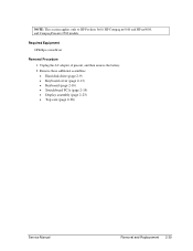
Unplug the AC adapter, if present, and then remove the battery. 2. Remove these additional assemblies: • Hard disk drive (page 2-9) • Keyboard cover (page 2-13) • Keyboard (page 2-16) • Switchboard PCA (page 2-19) • Display assembly (page 2-23) • Top case (page 2-26) Service Manual Removal and Replacement 2-39 Required Equipment 0 Phillips screwdriver Removal Procedure 1. NOTE: This section applies only to HP Pavilion 5x00, HP Compaq nx9010 and HP nx9008, and Compaq Presario 2500 models.
Unplug the AC adapter, if present, and then remove the battery. 2. Remove these additional assemblies: • Hard disk drive (page 2-9) • Keyboard cover (page 2-13) • Keyboard (page 2-16) • Switchboard PCA (page 2-19) • Display assembly (page 2-23) • Top case (page 2-26) Service Manual Removal and Replacement 2-39 Required Equipment 0 Phillips screwdriver Removal Procedure 1. NOTE: This section applies only to HP Pavilion 5x00, HP Compaq nx9010 and HP nx9008, and Compaq Presario 2500 models.
Maintenance and Service Guide
Page 71
... to HP Pavilion 4x00, HP Compaq nx9005 and nx9000, Compaq Evo Notebook N1050v and N1010v, and Compaq Presario 2100 and 1100 models. Unplug the AC adapter, if present, and then remove the battery. 2. Remove these additional assemblies: • Hard disk drive (page 2-9) • Keyboard cover (page 2-13) • Keyboard (page 2-16) • Switchboard PCA (page...
... to HP Pavilion 4x00, HP Compaq nx9005 and nx9000, Compaq Evo Notebook N1050v and N1010v, and Compaq Presario 2100 and 1100 models. Unplug the AC adapter, if present, and then remove the battery. 2. Remove these additional assemblies: • Hard disk drive (page 2-9) • Keyboard cover (page 2-13) • Keyboard (page 2-16) • Switchboard PCA (page...
Maintenance and Service Guide
Page 75
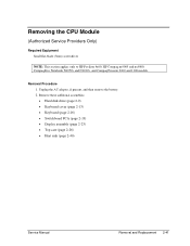
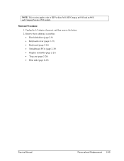
Remove these additional assemblies: • Hard disk drive (page 2-9) • Keyboard cover (page 2-13) • Keyboard (page 2-16) • Switchboard PCA (page 2-19) • Display assembly (page 2-23) • Top case (page 2-26) • Heat sink (page 2-40) Service Manual Removal and Replacement 2-45 Unplug the AC adapter, if present, and then remove the battery. 2. Removal Procedure 1. NOTE: This section applies only to HP Pavilion 5x00, HP Compaq nx9010 and nx9008, and Compaq Presario 2500 models.
Remove these additional assemblies: • Hard disk drive (page 2-9) • Keyboard cover (page 2-13) • Keyboard (page 2-16) • Switchboard PCA (page 2-19) • Display assembly (page 2-23) • Top case (page 2-26) • Heat sink (page 2-40) Service Manual Removal and Replacement 2-45 Unplug the AC adapter, if present, and then remove the battery. 2. Removal Procedure 1. NOTE: This section applies only to HP Pavilion 5x00, HP Compaq nx9010 and nx9008, and Compaq Presario 2500 models.
Maintenance and Service Guide
Page 77
... the hard disk drive guide. 4. Make sure these additional assemblies: • Hard disk drive (page 2-9) • Keyboard cover (page 2-13) • Keyboard (page 2-16) • Switchboard PCA (page 2-19) • Display assembly (page 2-23) • Top case (page 2-26) • Heat sink (page 2-40) 3. Disconnect the modem cable from the motherboard. Remove... the 4 screws that secure the hard disk drive guide are M2.0×4.0mm screws. NOTE: The 4 screws that secure the hard disk drive guide to HP Pavilion 5x00, HP Compaq nx9010 and nx9008, and Compaq Presario 2500 models.
... the hard disk drive guide. 4. Make sure these additional assemblies: • Hard disk drive (page 2-9) • Keyboard cover (page 2-13) • Keyboard (page 2-16) • Switchboard PCA (page 2-19) • Display assembly (page 2-23) • Top case (page 2-26) • Heat sink (page 2-40) 3. Disconnect the modem cable from the motherboard. Remove... the 4 screws that secure the hard disk drive guide are M2.0×4.0mm screws. NOTE: The 4 screws that secure the hard disk drive guide to HP Pavilion 5x00, HP Compaq nx9010 and nx9008, and Compaq Presario 2500 models.
Maintenance and Service Guide
Page 91
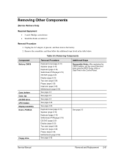
...Case, top CD/DVD drive CPU module Display assembly Doors, PCMCIA Floppy drive Removal Procedure Keyboard cover(page 2-13) Speaker (page 2-15) Keyboard (page 2-16) Switchboard PCA(page 2-19) CD/DVD (page 2-20 Display (page 2-23) Top case (page 2-26) Floppy (page 2-32) Heat sink (page 2-40) Motherboard ... 2-50) See page 2-3 See page 2-3 See page 2-3 See page 2-44 See page 2-23. Keyboard cover(page 2-13) Speaker (page 2-15) Keyboard (page 2-16) Switchboard PCA(page 2-19) CD/DVD (page 2-20 Display (page 2-23) Top case (page 2-26) Heat sink (page 2-40) Floppy (page 2-32) Motherboard (page 2-50)...
...Case, top CD/DVD drive CPU module Display assembly Doors, PCMCIA Floppy drive Removal Procedure Keyboard cover(page 2-13) Speaker (page 2-15) Keyboard (page 2-16) Switchboard PCA(page 2-19) CD/DVD (page 2-20 Display (page 2-23) Top case (page 2-26) Floppy (page 2-32) Heat sink (page 2-40) Motherboard ... 2-50) See page 2-3 See page 2-3 See page 2-3 See page 2-44 See page 2-23. Keyboard cover(page 2-13) Speaker (page 2-15) Keyboard (page 2-16) Switchboard PCA(page 2-19) CD/DVD (page 2-20 Display (page 2-23) Top case (page 2-26) Heat sink (page 2-40) Floppy (page 2-32) Motherboard (page 2-50)...

Maintenance and Service Guide
Page 92
... 2-20 Display (page 2-23) Top case (page 2-26 See page page 2-32 See page 2-3 Keyboard cover(page 2-13) Speaker (page 2-15) Keyboard (page 2-16) Switchboard PCA(page 2-19) CD/DVD (page 2-20 Display (page 2-23) Top case (page 2-26) See page 2-36 Keyboard cover(page 2-13) Speaker (page 2-15) Keyboard (...page 2-16) Switchboard PCA(page 2-19) CD/DVD (page 2-20 Display (page 2-23) Top case (page 2-26) Floppy (page 2-32) Heat sink (page 2-40) Motherboard (page 2-50) Bottom...
... 2-20 Display (page 2-23) Top case (page 2-26 See page page 2-32 See page 2-3 Keyboard cover(page 2-13) Speaker (page 2-15) Keyboard (page 2-16) Switchboard PCA(page 2-19) CD/DVD (page 2-20 Display (page 2-23) Top case (page 2-26) See page 2-36 Keyboard cover(page 2-13) Speaker (page 2-15) Keyboard (...page 2-16) Switchboard PCA(page 2-19) CD/DVD (page 2-20 Display (page 2-23) Top case (page 2-26) Floppy (page 2-32) Heat sink (page 2-40) Motherboard (page 2-50) Bottom...