ProtectTools (Select Models Only) - Windows Vista
Page 58
...unlock the computer. NOTE This option is available only if the Credential Manager classic logon prompt is displayed. Select Start > All Programs > HP ProtectTools Security Manager. 2. You must use Credential Manager to log on to Windows, either at a local computer or on to Credential Manager....the system automatically adds your Windows account and to Windows using Credential Manager. If you will be logged on to Windows, click the keyboard icon in the Password box and click Next. 5. Select More > Wizard Options. If your authentication information is correct, you have ...
...unlock the computer. NOTE This option is available only if the Credential Manager classic logon prompt is displayed. Select Start > All Programs > HP ProtectTools Security Manager. 2. You must use Credential Manager to log on to Windows, either at a local computer or on to Credential Manager....the system automatically adds your Windows account and to Windows using Credential Manager. If you will be logged on to Windows, click the keyboard icon in the Password box and click Next. 5. Select More > Wizard Options. If your authentication information is correct, you have ...
External Devices
Page 3
Low power devices such as a USB keyboard, mouse, drive, printer, scanner, or hub, to the computer or to an optional docking device. External Devices 1-1 An optional docking device provides additional USB ports ... 2 USB ports do not require an AC power connection when connected to external devices when used to connect an optional external device, such as USB keyboards, mouse devices, and webcams do not provide power.
Low power devices such as a USB keyboard, mouse, drive, printer, scanner, or hub, to the computer or to an optional docking device. External Devices 1-1 An optional docking device provides additional USB ports ... 2 USB ports do not require an AC power connection when connected to external devices when used to connect an optional external device, such as USB keyboards, mouse devices, and webcams do not provide power.
External Devices
Page 6
... on the computer during startup or in the lower-left corner of the screen. 2. Open Computer Setup by default) allows you to ■ Use a USB keyboard, mouse, or hub connected to select File > Save changes and exit. Using a USB device USB legacy support USB legacy support (enabled by turning on or...
... on the computer during startup or in the lower-left corner of the screen. 2. Open Computer Setup by default) allows you to ■ Use a USB keyboard, mouse, or hub connected to select File > Save changes and exit. Using a USB device USB legacy support USB legacy support (enabled by turning on or...

External Devices - Windows Vista
Page 3
... additional USB ports for the system and can be connected to the computer or to AC power. External Devices 1-1 Low power devices such as a USB keyboard, mouse, drive, printer, scanner, or hub, to the computer or to an optional docking device. 1 Using a USB device Universal Serial Bus (USB) ...is a hardware interface that can be used to connect an optional external device, such as USB keyboards, mouse devices, and webcams do not require an AC power connection when connected to the 2 USB ports that do not provide power. This computer has...
... additional USB ports for the system and can be connected to the computer or to AC power. External Devices 1-1 Low power devices such as a USB keyboard, mouse, drive, printer, scanner, or hub, to the computer or to an optional docking device. 1 Using a USB device Universal Serial Bus (USB) ...is a hardware interface that can be used to connect an optional external device, such as USB keyboards, mouse devices, and webcams do not require an AC power connection when connected to the 2 USB ports that do not provide power. This computer has...

External Devices - Windows Vista
Page 6
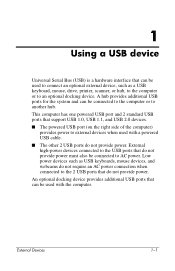
... on the computer during startup or in the lower-left corner of the screen. 2. Open Computer Setup by default) allows you to ■ Use a USB keyboard, mouse, or hub connected to enable or disable USB legacy support, and then press f10. 4. Using a USB device USB legacy support USB legacy support (enabled...
... on the computer during startup or in the lower-left corner of the screen. 2. Open Computer Setup by default) allows you to ■ Use a USB keyboard, mouse, or hub connected to enable or disable USB legacy support, and then press f10. 4. Using a USB device USB legacy support USB legacy support (enabled...
Memory Modules
Page 3
... all battery packs before installing a memory module. Ä CAUTION: Electrostatic discharge (ESD) can damage electronic components. The expansion memory module compartment is located under the keyboard. The memory capacity of the computer. Memory Modules 1-1
... all battery packs before installing a memory module. Ä CAUTION: Electrostatic discharge (ESD) can damage electronic components. The expansion memory module compartment is located under the keyboard. The memory capacity of the computer. Memory Modules 1-1
Memory Modules
Page 11
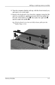
Turn the computer display-side up on the display hinge covers. Remove the keyboard cover from the computer using the flat end of a screwdriver, applying pressure first from under the left side of the button cover 1, then under the right side 2, and last under the middle 3. ✎ If the keyboard cover does not fully release, pull up , with the front toward you, and open it at a wide angle. 9. Adding or replacing memory modules 8. Memory Modules 1-9
Turn the computer display-side up on the display hinge covers. Remove the keyboard cover from the computer using the flat end of a screwdriver, applying pressure first from under the left side of the button cover 1, then under the right side 2, and last under the middle 3. ✎ If the keyboard cover does not fully release, pull up , with the front toward you, and open it at a wide angle. 9. Adding or replacing memory modules 8. Memory Modules 1-9
Memory Modules
Page 12
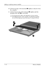
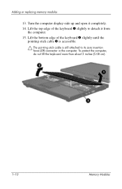
Lift the bottom edge of the keyboard 1 slightly to its zero insertion force (ZIF) connector in the computer. To protect the computer, do not lift the keyboard more than about 2 inches (5.08 cm). 1-10 Memory Modules Lift the top edge of the keyboard 2 slightly until the pointing stick cable 3 is accessible. Ä The pointing stick cable is still attached to detach it from the computer. 11. Adding or replacing memory modules 10.
Lift the bottom edge of the keyboard 1 slightly to its zero insertion force (ZIF) connector in the computer. To protect the computer, do not lift the keyboard more than about 2 inches (5.08 cm). 1-10 Memory Modules Lift the top edge of the keyboard 2 slightly until the pointing stick cable 3 is accessible. Ä The pointing stick cable is still attached to detach it from the computer. 11. Adding or replacing memory modules 10.

Memory Modules
Page 14
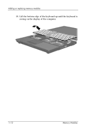
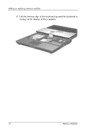
Lift the bottom edge of the keyboard up until the keyboard is resting on the display of the computer. 1-12 Memory Modules Adding or replacing memory modules 14.
Lift the bottom edge of the keyboard up until the keyboard is resting on the display of the computer. 1-12 Memory Modules Adding or replacing memory modules 14.
Memory Modules
Page 18
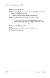
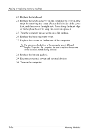
Replace the keyboard. 20. Replace the battery pack(s). 24. Replace the screws on the bottom of the computer. Ä The screws on the computer. 1-16 Memory Modules To protect the computer, be sure to replace the screws into the locations noted during removal. 23. Reconnect external power and external devices. 25. Turn on the bottom of the computer are of different lengths. Replace the keyboard cover on a flat surface. 22. Turn the computer upside down on the computer by reversing the steps for removing the cover. 21. Adding or replacing memory modules 19.
Replace the keyboard. 20. Replace the battery pack(s). 24. Replace the screws on the bottom of the computer. Ä The screws on the computer. 1-16 Memory Modules To protect the computer, be sure to replace the screws into the locations noted during removal. 23. Reconnect external power and external devices. 25. Turn on the bottom of the computer are of different lengths. Replace the keyboard cover on a flat surface. 22. Turn the computer upside down on the computer by reversing the steps for removing the cover. 21. Adding or replacing memory modules 19.

Memory Modules
Page 3
Memory Modules 1-1 The expansion memory module compartment is located under the keyboard. The memory capacity of the computer can be upgraded by adding a memory module to the vacant expansion memory module slot or by touching a grounded metal ...
Memory Modules 1-1 The expansion memory module compartment is located under the keyboard. The memory capacity of the computer can be upgraded by adding a memory module to the vacant expansion memory module slot or by touching a grounded metal ...

Memory Modules
Page 10
Turn the computer display-side up the right rear corner edge 1 and then the left rear corner edge 2 of the keyboard cover to release the front edge of the cover from the computer. 1-8 Memory Modules Tilt the keyboard cover up from the front edge 3 to release the rear edge of the cover from the computer. 11. Lift up , with the front toward you and open it. 10. Adding or replacing memory modules 9.
Turn the computer display-side up the right rear corner edge 1 and then the left rear corner edge 2 of the keyboard cover to release the front edge of the cover from the computer. 1-8 Memory Modules Tilt the keyboard cover up from the front edge 3 to release the rear edge of the cover from the computer. 11. Lift up , with the front toward you and open it. 10. Adding or replacing memory modules 9.
Memory Modules
Page 11
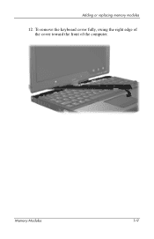
Memory Modules 1-9 To remove the keyboard cover fully, swing the right edge of the cover toward the front of the computer. Adding or replacing memory modules 12.
Memory Modules 1-9 To remove the keyboard cover fully, swing the right edge of the cover toward the front of the computer. Adding or replacing memory modules 12.
Memory Modules
Page 12
To protect the computer, do not lift the keyboard more than about 2 inches (5.08 cm). 1-10 Memory Modules Lift the top edge of the keyboard 2 slightly until the pointing stick cable 3 is accessible. Ä The pointing stick cable is still attached to detach it completely. 14. Lift the bottom edge of the keyboard 1 slightly to its zero insertion force (ZIF) connector in the computer. Turn the computer display-side up and open it from the computer. 15. Adding or replacing memory modules 13.
To protect the computer, do not lift the keyboard more than about 2 inches (5.08 cm). 1-10 Memory Modules Lift the top edge of the keyboard 2 slightly until the pointing stick cable 3 is accessible. Ä The pointing stick cable is still attached to detach it completely. 14. Lift the bottom edge of the keyboard 1 slightly to its zero insertion force (ZIF) connector in the computer. Turn the computer display-side up and open it from the computer. 15. Adding or replacing memory modules 13.
Memory Modules
Page 14
Adding or replacing memory modules 18. Lift the bottom edge of the keyboard up until the keyboard is resting on the display of the computer. 1-12 Memory Modules
Adding or replacing memory modules 18. Lift the bottom edge of the keyboard up until the keyboard is resting on the display of the computer. 1-12 Memory Modules
Memory Modules
Page 18
... on the bottom of the computer are of the cover first, and then reseat the right side. Replace the keyboard. 24. To protect the computer, be sure to snap the cover into place.) 25. Replace the base enclosure cover. 27. Replace the screws on the ... for removing the cover. (Reseat the left side of different lengths. Reconnect external power and external devices. 30. Press along the front edge of the keyboard cover to replace the screws in the locations noted during removal. 28. Turn on a flat surface. 26.
... on the bottom of the computer are of the cover first, and then reseat the right side. Replace the keyboard. 24. To protect the computer, be sure to snap the cover into place.) 25. Replace the base enclosure cover. 27. Replace the screws on the ... for removing the cover. (Reseat the left side of different lengths. Reconnect external power and external devices. 30. Press along the front edge of the keyboard cover to replace the screws in the locations noted during removal. 28. Turn on a flat surface. 26.
Memory Modules - Windows Vista
Page 3
The expansion memory module compartment is located under the keyboard. Before beginning any procedure, ensure that you are discharged of static electricity by upgrading the existing memory module in this chapter. Adding or replacing memory ...
The expansion memory module compartment is located under the keyboard. Before beginning any procedure, ensure that you are discharged of static electricity by upgrading the existing memory module in this chapter. Adding or replacing memory ...

Memory Modules - Windows Vista
Page 11
Adding or replacing memory modules 9. Turn the computer display-side up on the display hinge covers. Remove the keyboard cover from the computer using the flat end of a screwdriver, applying pressure first from under the left side of the button cover 1, then under the right side 2, and last under the middle 3. ✎ If the keyboard cover does not fully release, pull up , with the front toward you, and open it at a wide angle. 10. Memory Modules 9
Adding or replacing memory modules 9. Turn the computer display-side up on the display hinge covers. Remove the keyboard cover from the computer using the flat end of a screwdriver, applying pressure first from under the left side of the button cover 1, then under the right side 2, and last under the middle 3. ✎ If the keyboard cover does not fully release, pull up , with the front toward you, and open it at a wide angle. 10. Memory Modules 9

Memory Modules - Windows Vista
Page 12
Lift the bottom edge of the keyboard 1 slightly to its zero insertion force (ZIF) connector in the computer. Lift the top edge of the keyboard 2 slightly until the pointing stick cable 3 is accessible. Ä The pointing stick cable is still attached to detach it from the computer. 12. To protect the computer, do not lift the keyboard more than about 2 inches (5.08 cm). 10 Memory Modules Adding or replacing memory modules 11.
Lift the bottom edge of the keyboard 1 slightly to its zero insertion force (ZIF) connector in the computer. Lift the top edge of the keyboard 2 slightly until the pointing stick cable 3 is accessible. Ä The pointing stick cable is still attached to detach it from the computer. 12. To protect the computer, do not lift the keyboard more than about 2 inches (5.08 cm). 10 Memory Modules Adding or replacing memory modules 11.
Memory Modules - Windows Vista
Page 14
Adding or replacing memory modules 15. Lift the bottom edge of the keyboard up until the keyboard is resting on the display of the computer. 12 Memory Modules
Adding or replacing memory modules 15. Lift the bottom edge of the keyboard up until the keyboard is resting on the display of the computer. 12 Memory Modules

