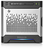
Error Prevention Guide
Page 7
... you have a tape drive, maintain a scheduled cleaning program. • If you took to the server) include SCSI controllers, hot-pluggable redundant power supplies, hot-pluggable fans, hot-pluggable drives, SCSI cables, network adapters, Processor Power Modules (PPMs), and perhaps even complete I/O, media, processor, and memory modules, if the server is modular...
Error Prevention Guide
Page 8
...they are in the server documentation before removing, replacing, reseating, or modifying system components. • Check for adequate airflow and dislodge anything blocking the fans. • Check for frays. CAUTION: To avoid potential problems, always read the cautionary information in need of repair. • Take the system... of compressed air, tighten any loose connections, reseat boards, and inspect any dust buildup with high-current machines, such as fans. • Check the server after power disruptions due to counter excessive demand on its generation and distribution system).
Memory technology evolution: an overview of system memory technologies, 8th Edition
Page 17
..., increases due to the point-to the channel, the total transmission latency increases. An FB-DIMM consumes almost 5 Watts more efficiently by the server's internal fans (Figure 16). Memory latency is the delay from the time the data is serialized prior to transmission, and then de-serialized after it can be...
HP ProLiant MicroServer Gen8 Maintenance and Service Guide
Page 3
... from the flash-backed write cache 37 Front I/O module assembly ...37 Ambient temperature sensor cable ...40 LFF non-hot-plug drive cage bracket ...41 System fan...45 Integrated power supply ...46 Expansion board...47 DIMMs ...48 General DIMM slot population guidelines 48 Removing a DIMM ...49 Heatsink ...49 Processor...51 System board...
HP ProLiant MicroServer Gen8 Maintenance and Service Guide
Page 4
...69 DIMM slot locations...71 System maintenance switch ...71 NMI functionality ...72 Drive numbering ...72 FBWC module LED definitions ...73 Fan location ...74 T-10/T-15 Torx screwdriver ...74 Cabling ...75 Cabling overview...75 Four-bay LFF non-hot-plug drive ...77 Front I/O assembly cabling...77 Ambient temperature sensor cabling ...78 System fan cabling ...78 Power supply cabling ...79 Specifications ...80 Environmental specifications ...80 Server specifications ...80 Power supply specifications...80 HP 150 W Integrated Power Supply 80 Acronyms and abbreviations...82 Documentation feedback ......
HP ProLiant MicroServer Gen8 Maintenance and Service Guide
Page 28
... board, the gray connectors correspond to a storage controller board, disconnect the Mini-SAS cable from the board. 7. Disconnect all cables connected to disconnect the cable) o Fan cable o Ambient temperature sensor cable (pulling up the server. o 24-pin system board power supply cable o SATA cable (only if an optical drive is installed...
HP ProLiant MicroServer Gen8 Maintenance and Service Guide
Page 45
c. To replace the component, reverse the removal procedure. Power down the server (on page 26). 5. Remove the chassis cover (on page 23). 2. To replace the component, reverse the removal procedure. Disconnect the fan cable. 6. Disconnect the power cord from the server. 4. Removal and replacement procedures 45 System fan To remove the component: 1. Remove the screws securing the system fan, and then remove the fan. Pull the bracket out of the chassis. Disconnect the power cord from the AC source. 3.
HP ProLiant MicroServer Gen8 Maintenance and Service Guide
Page 68
Component identification 68 The same information is printed on separate labels located on the rear panel. Rear panel components Item Description 1 Kensington security slot 2 Power supply 3 Serial number/iLO information tag* 4 Power cord connector 5 Dedicated iLO connector 6 Video connector 7 USB 3.0 connectors 8 USB 2.0 connectors 9 NIC connector 2 10 NIC connector 1/shared iLO connector 11 System fan * The serial number/iLO information tag shows the server serial number and the default iLO account information.
HP ProLiant MicroServer Gen8 Maintenance and Service Guide
Page 70
Item 1 2 3 4 5 6 7 8 9 10 11 12 13 14 15 Description Fan connector DIMM slots Front I/O connector Processor socket TPM connector System battery Mini-SAS connector Optical drive SATA connector Ambient temperature sensor connector 24-pin system board power connector Internal USB 2.0 connector microSD card slot NMI header PCIe2 x16 (8, 4, 1) slot System maintenance switch Component identification 70
HP ProLiant MicroServer Gen8 Maintenance and Service Guide
Page 74
Component identification 74 Fan location The server has one system fan located at the rear of the server. T-10/T-15 Torx screwdriver The server includes a T-10/T-15 Torx screwdriver located on the front panel. Use this screwdriver to loosen screws during hardware configuration procedures.
HP ProLiant MicroServer Gen8 Maintenance and Service Guide
Page 78
Ambient temperature sensor cabling System fan cabling Cabling 78
HP ProLiant MicroServer Gen8 Maintenance and Service Guide
Page 85
... determining status of 67 E electrostatic discharge 21 environmental specifications 80 error messages 62 expansion board 47 external USB functionality 65 F fan cabling 78 fan location 74 FBWC module 34 FBWC module LEDs 73 flash-backed write cache procedures front bezel 24 front I/O assembly 37 front ...I/O cabling 77 front panel buttons 67 front panel components 66 front panel LEDs 67 34, 37 H health driver 65 health LED 67 heatsink 49 HP Insight Diagnostics 63 HP...
HP ProLiant MicroServer Gen8 Maintenance and Service Guide
Page 86
..., installing 30 system board assembly, removing 28 system board components 69 system board replacement 53 system components 18, 66 system configuration settings 71 system fan 45, 74 system fan cabling 78 system maintenance switch 71 T T-10/T-15 Torx screwdriver 74 temperature requirements 80 TPM connector 69 troubleshooting resources 62 Trusted Platform Module...
HP ProLiant MicroServer Gen8 User Guide
Page 3
...buttons...9 System board components ...9 DIMM slot locations ...11 System maintenance switch...11 NMI functionality...12 Drive numbering ...12 FBWC module LED definitions...13 Fan location ...14 T-10/T-15 Torx screwdriver ...14 Operations...15 Power up the server ...15 Power down the server...15 Open the front bezel...16... ...28 Powering on and selecting boot options ...29 Performing the initial system setup ...30 Registering the server ...34 Setting up the HP PS1810-8G Switch (optional 34 Hardware options installation...41 Introduction ...41 Bezel faceplate ...41 Drive options ...43 Contents 3
HP ProLiant MicroServer Gen8 User Guide
Page 4
... controller ...46 Installing the FBWC module and capacitor pack 47 Optical drive option ...49 Memory options ...52 HP SmartMemory ...52 DIMM identification ...52 Single-rank and dual-rank DIMMs ...53 Memory subsystem architecture ...53 ECC...fan cabling ...63 Power supply cabling...64 Software and configuration utilities 65 Server mode ...65 HP product QuickSpecs...65 HP iLO Management Engine ...65 HP iLO ...65 Intelligent Provisioning...67 HP Insight Remote Support software 69 HP Insight Online ...69 Scripting Toolkit ...69 HP Service Pack for ProLiant ...70 HP Smart Update Manager...70 HP...
HP ProLiant MicroServer Gen8 User Guide
Page 8
Rear panel components Item Description 1 Kensington security slot 2 Power supply 3 Serial number/iLO information tag* 4 Power cord connector 5 Dedicated iLO 4 connector 6 Video connector 7 USB 3.0 connectors 8 USB 2.0 connectors 9 NIC connector 2 10 NIC connector 1/shared iLO 4 connector 11 System fan * The serial number/iLO information tag shows the server serial number and the default iLO account information. Component identification 8 The same information is printed on separate labels located on the rear panel.
HP ProLiant MicroServer Gen8 User Guide
Page 10
Item 1 2 3 4 5 6 7 8 9 10 11 12 13 14 15 Description Fan connector DIMM slots Front I/O connector Processor socket TPM connector System battery Mini-SAS connector Optical drive SATA connector Ambient temperature sensor connector 24-pin system board power connector Internal USB 2.0 connector microSD card slot NMI header PCIe2 x16 (8, 4, 1) slot System maintenance switch Component identification 10
HP ProLiant MicroServer Gen8 User Guide
Page 14
Use this screwdriver to loosen screws during hardware configuration procedures. Component identification 14 Fan location The server has one system fan located at the rear of the server. T-10/T-15 Torx screwdriver The server includes a T-10/T-15 Torx screwdriver located on the front panel.
HP ProLiant MicroServer Gen8 User Guide
Page 20
o Connect the server to the switch ("Setting up the HP PS1810-8G Switch (optional)" on page 15). Power up the brown loop to the server ("Connecting the power cord" on page 19). 5. o 24-pin system ... the Mini-SAS cable from the board. 7. It is connected to the system board) o Front I/O cable (pulling up the blue loop to disconnect the cable) o Fan cable o Ambient temperature sensor cable (pulling up the server (on page 34). 6. If the drive cage is connected to the network. Do one of the...
HP ProLiant MicroServer Gen8 User Guide
Page 63
Ambient temperature sensor cabling System fan cabling Cabling 63