ProLiant DL170e G6 Server - HP
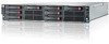
ProLiant DL170e G6 Server
View Results Below
Free HP ProLiant DL170e manuals!
Problems with HP ProLiant DL170e?
Ask a Question
Free HP ProLiant DL170e manuals!
Problems with HP ProLiant DL170e?
Ask a Question
Related Manual Pages


Similar Questions

How Do I Locate Dl180 G6 Series Server's Maintenance Switches
I have a problem that I have installed Centos 5.11 at my HP DL180 G6 series and it is failing to boo...
I have a problem that I have installed Centos 5.11 at my HP DL180 G6 series and it is failing to boo...
(Posted by lmbenje 9 years ago)

Does A Hp Smartstart Disk Come With Hp Proliant Dl180 G6 Server
(Posted by mismb 9 years ago)

How To Find Product Number Proliant Dl380 G6 Server
(Posted by dwc19soj 9 years ago)