End User License Agreement
Page 2
...limited to the original Software Product provided by the Microsoft License Agreement. 2. UPGRADES. The transfer may no longer use of the HP Product with the update or supplement. PROPRIETARY RIGHTS. LIMITATION ON REVERSE ENGINEERING. Recovery Solution. The initial user of the Software Product ...may not reverse engineer, decompile, or disassemble the Software Product, except and only to the extent that the right to the You shall not remove any other terms will ...
...limited to the original Software Product provided by the Microsoft License Agreement. 2. UPGRADES. The transfer may no longer use of the HP Product with the update or supplement. PROPRIETARY RIGHTS. LIMITATION ON REVERSE ENGINEERING. Recovery Solution. The initial user of the Software Product ...may not reverse engineer, decompile, or disassemble the Software Product, except and only to the extent that the right to the You shall not remove any other terms will ...

Maintenance and Service Guide
Page 1
It provides comprehensive information on identifying computer features, components, and spare parts, troubleshooting computer problems, and performing computer disassembly procedures. b Maintenance and Service Guide Compaq Evo Notebook N1020v Series Compaq Evo Notebook N1000v Series Compaq Presario 1500 Series Mobile PC Document Part Number: 279372-002 November 2002 This guide is a troubleshooting reference used for maintaining and servicing the notebook.
It provides comprehensive information on identifying computer features, components, and spare parts, troubleshooting computer problems, and performing computer disassembly procedures. b Maintenance and Service Guide Compaq Evo Notebook N1020v Series Compaq Evo Notebook N1000v Series Compaq Presario 1500 Series Mobile PC Document Part Number: 279372-002 November 2002 This guide is a troubleshooting reference used for maintaining and servicing the notebook.

Maintenance and Service Guide
Page 4
... to Removable Drives 4-3 4.4 Preventing Electrostatic Damage 4-4 4.5 Packaging and Transporting Precautions 4-4 4.6 Workstation Precautions 4-5 4.7 Grounding Equipment and Methods 4-6 5 Removal and Replacement Procedures 5.1 Serial Number 5-2 5.2 Disassembly Sequence Chart 5-3 5.3 Preparing the Computer for Disassembly 5-4 5.4 Computer Feet 5-13 5.5 Memory Expansion Board 5-13 5.6 Mini PCI Communications Board 5-15 5.7 Disk Cell RTC Battery 5-18 5.8 Connector Cover 5-19 5.9 LED Cover...
... to Removable Drives 4-3 4.4 Preventing Electrostatic Damage 4-4 4.5 Packaging and Transporting Precautions 4-4 4.6 Workstation Precautions 4-5 4.7 Grounding Equipment and Methods 4-6 5 Removal and Replacement Procedures 5.1 Serial Number 5-2 5.2 Disassembly Sequence Chart 5-3 5.3 Preparing the Computer for Disassembly 5-4 5.4 Computer Feet 5-13 5.5 Memory Expansion Board 5-13 5.6 Mini PCI Communications Board 5-15 5.7 Disk Cell RTC Battery 5-18 5.8 Connector Cover 5-19 5.9 LED Cover...
Maintenance and Service Guide
Page 34
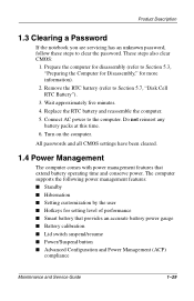
...computer. 5. The computer supports the following power management features: ■ Standby ■ Hibernation ■ Setting customization by the user ■ Hotkeys for disassembly (refer to Section 5.7, "Disk Cell RTC Battery"). 3. Wait approximately five minutes. 4. Prepare the computer for setting level of performance ■ Smart battery...) compliance Maintenance and Service Guide 1-29 Connect AC power to clear the password. Product Description 1.3 Clearing a Password If the notebook you are servicing has an unknown password, follow these steps to the computer.
...computer. 5. The computer supports the following power management features: ■ Standby ■ Hibernation ■ Setting customization by the user ■ Hotkeys for disassembly (refer to Section 5.7, "Disk Cell RTC Battery"). 3. Wait approximately five minutes. 4. Prepare the computer for setting level of performance ■ Smart battery...) compliance Maintenance and Service Guide 1-29 Connect AC power to clear the password. Product Description 1.3 Clearing a Password If the notebook you are servicing has an unknown password, follow these steps to the computer.
Maintenance and Service Guide
Page 45
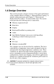
... stick ■ Audio ■ Intel Mobile Pentium 4 processors with SpeedStep technology or Intel Celeron processors ■ Fan ■ PC Card ■ Modem or modem/NIC The computer uses an electrical fan for disassembly steps. Refer to Chapter 3, "Illustrated Parts Catalog," to turn on the left and right sides of the computer. Exhaust...
... stick ■ Audio ■ Intel Mobile Pentium 4 processors with SpeedStep technology or Intel Celeron processors ■ Fan ■ PC Card ■ Modem or modem/NIC The computer uses an electrical fan for disassembly steps. Refer to Chapter 3, "Illustrated Parts Catalog," to turn on the left and right sides of the computer. Exhaust...

Maintenance and Service Guide
Page 101
...whenever possible. Apply only the tension required to avoid damage. Handle flex cables with extreme care to unseat or seat the cables during disassembly and assembly procedures. ✎ As you remove each subassembly from the computer, place the subassembly (and all cases, avoid bending,.... these cables tear easily. Ä CAUTION: When servicing the computer, ensure that cables are routed in their proper locations during disassembly and reassembly can damage the computer. 4-2 Maintenance and Service Guide In all accompanying screws) away from the work area to prevent damage...
...whenever possible. Apply only the tension required to avoid damage. Handle flex cables with extreme care to unseat or seat the cables during disassembly and assembly procedures. ✎ As you remove each subassembly from the computer, place the subassembly (and all cases, avoid bending,.... these cables tear easily. Ä CAUTION: When servicing the computer, ensure that cables are routed in their proper locations during disassembly and reassembly can damage the computer. 4-2 Maintenance and Service Guide In all accompanying screws) away from the work area to prevent damage...

Maintenance and Service Guide
Page 109
... number to remove the hard drive from hard drive bracket 0 1 1 0 2 2 0 7 0 6 6 3 Maintenance and Service Guide 5-3 Section 5.3 5.4 5.5 5.6 5.7 5.8 5.9 5.10 5.11 5.12 5.13 5.14 5.15 Disassembly Sequence Chart Description Preparing the computer for disassembly Battery pack Optical drive Hard drive Computer feet Memory expansion board Mini PCI communications board Disk cell RTC battery Connector cover LED...
... number to remove the hard drive from hard drive bracket 0 1 1 0 2 2 0 7 0 6 6 3 Maintenance and Service Guide 5-3 Section 5.3 5.4 5.5 5.6 5.7 5.8 5.9 5.10 5.11 5.12 5.13 5.14 5.15 Disassembly Sequence Chart Description Preparing the computer for disassembly Battery pack Optical drive Hard drive Computer feet Memory expansion board Mini PCI communications board Disk cell RTC battery Connector cover LED...

Maintenance and Service Guide
Page 110
Removal and Replacement Procedures Section 5.16 5.17 5.18 5.19 5.20 5.21 5.22 5.23 Disassembly Sequence Chart (Continued) Description TouchPad and TouchButton Display release assembly Charger board Speaker assembly Top cover Fan System board Modem cable # of Screws Removed 4 on TouchPad models 5 on Dual Stick models 2 3 0 5 0 7 1 5.3 Preparing the Computer for Disassembly Perform the following steps before disassembling the computer: 1. Turn off the computer. 2. Disconnect the AC adapter and all external devices. 5-4 Maintenance and Service Guide
Removal and Replacement Procedures Section 5.16 5.17 5.18 5.19 5.20 5.21 5.22 5.23 Disassembly Sequence Chart (Continued) Description TouchPad and TouchButton Display release assembly Charger board Speaker assembly Top cover Fan System board Modem cable # of Screws Removed 4 on TouchPad models 5 on Dual Stick models 2 3 0 5 0 7 1 5.3 Preparing the Computer for Disassembly Perform the following steps before disassembling the computer: 1. Turn off the computer. 2. Disconnect the AC adapter and all external devices. 5-4 Maintenance and Service Guide

Maintenance and Service Guide
Page 119
... Information 512 MB 256 MB 128 MB 285524-001 285523-001 285222-001 1. The computer feet are adhesive-backed rubber pads. Prepare the computer for disassembly (Section 5.3). 2. Turn the computer bottom side up with the front facing forward.
... Information 512 MB 256 MB 128 MB 285524-001 285523-001 285222-001 1. The computer feet are adhesive-backed rubber pads. Prepare the computer for disassembly (Section 5.3). 2. Turn the computer bottom side up with the front facing forward.

Maintenance and Service Guide
Page 122
... part number 285541-001. 5-16 Maintenance and Service Guide Remove the cover. Turn the computer bottom side up with carbon finish for Evo Notebook N1020v and N1000v models and silver finish for disassembly (Section 5.3). 2. Lift the left 2. 5. Figure 5-12. Removal and Replacement Procedures 1. Prepare the computer for Presario 1500 models, and are available with...
... part number 285541-001. 5-16 Maintenance and Service Guide Remove the cover. Turn the computer bottom side up with carbon finish for Evo Notebook N1020v and N1000v models and silver finish for disassembly (Section 5.3). 2. Lift the left 2. 5. Figure 5-12. Removal and Replacement Procedures 1. Prepare the computer for Presario 1500 models, and are available with...

Maintenance and Service Guide
Page 124
Remove the mini PCI compartment cover (Section 5.6). 3. Figure 5-14. Removing the Disk Cell RTC Battery ✎ The computer uses a CR1220 lithium disk cell battery. When replacing the RTC battery, insert the battery with the "+" sign facing up. 5-18 Maintenance and Service Guide Prepare the computer for disassembly (Section 5.3). 2. Remove the RTC battery from its socket on the system board (Figure 5-14). Removal and Replacement Procedures 5.7 Disk Cell RTC Battery Disk Cell RTC Battery Spare Part Number Information Disk cell RTC battery 279769-001 1.
Remove the mini PCI compartment cover (Section 5.6). 3. Figure 5-14. Removing the Disk Cell RTC Battery ✎ The computer uses a CR1220 lithium disk cell battery. When replacing the RTC battery, insert the battery with the "+" sign facing up. 5-18 Maintenance and Service Guide Prepare the computer for disassembly (Section 5.3). 2. Remove the RTC battery from its socket on the system board (Figure 5-14). Removal and Replacement Procedures 5.7 Disk Cell RTC Battery Disk Cell RTC Battery Spare Part Number Information Disk cell RTC battery 279769-001 1.

Maintenance and Service Guide
Page 125
... Procedures 5.8 Connector Cover ✎ The connector cover is available with the rear panel facing forward. 3. Turn the computer bottom side up with carbon finish for Evo Notebook N1020v and N1000v models and silver finish for disassembly (Section 5.3). 2. Figure 5-15.
... Procedures 5.8 Connector Cover ✎ The connector cover is available with the rear panel facing forward. 3. Turn the computer bottom side up with carbon finish for Evo Notebook N1020v and N1000v models and silver finish for disassembly (Section 5.3). 2. Figure 5-15.

Maintenance and Service Guide
Page 126
... 295736-001 1. Prepare the computer for use only with Evo Notebook N1000v models and Presario 1500 models with config. Removal and Replacement Procedures 5.9 LED Cover LED Cover Spare Part Number Information LED cover for disassembly (Section 5.3). 2. codes beginning with "L" for use only with Evo Notebook N1020v models and Presario 1500 models with config. codes beginning with...
... 295736-001 1. Prepare the computer for use only with Evo Notebook N1000v models and Presario 1500 models with config. Removal and Replacement Procedures 5.9 LED Cover LED Cover Spare Part Number Information LED cover for disassembly (Section 5.3). 2. codes beginning with "L" for use only with Evo Notebook N1020v models and Presario 1500 models with config. codes beginning with...

Maintenance and Service Guide
Page 129
Remove the LED cover (Section 5.9). 3. Figure 5-18. Prepare the computer for disassembly (Section 5.3). 2. Releasing the Keyboard Maintenance and Service Guide 5-23 Lift the back edge of the keyboard and swing it forward until it rests on the palm rest (Figure 5-18). Removal and Replacement Procedures 1.
Remove the LED cover (Section 5.9). 3. Figure 5-18. Prepare the computer for disassembly (Section 5.3). 2. Releasing the Keyboard Maintenance and Service Guide 5-23 Lift the back edge of the keyboard and swing it forward until it rests on the palm rest (Figure 5-18). Removal and Replacement Procedures 1.

Maintenance and Service Guide
Page 131
Remove the LED cover (Section 5.9). 3. Maintenance and Service Guide 5-25 Removal and Replacement Procedures 5.11 Heat Spreader Heat Spreaders Spare Part Number Information For use only on Evo Notebook N1020v and N1000v models For use only on Presario 1500 models 291648-001 285544-001 1. Prepare the computer for disassembly (Section 5.3). 2. Remove the keyboard (Section 5.10).
Remove the LED cover (Section 5.9). 3. Maintenance and Service Guide 5-25 Removal and Replacement Procedures 5.11 Heat Spreader Heat Spreaders Spare Part Number Information For use only on Evo Notebook N1020v and N1000v models For use only on Presario 1500 models 291648-001 285544-001 1. Prepare the computer for disassembly (Section 5.3). 2. Remove the keyboard (Section 5.10).

Maintenance and Service Guide
Page 134
...-001 285518-001 285517-001 303725-001 303724-001 311625-001 301643-001 303528-001 1. Keyboard (Section 5.10) c. LED cover (Section 5.9) b. Prepare the computer for disassembly (Section 5.3) and remove the following components: a.
...-001 285518-001 285517-001 303725-001 303724-001 311625-001 301643-001 303528-001 1. Keyboard (Section 5.10) c. LED cover (Section 5.9) b. Prepare the computer for disassembly (Section 5.3) and remove the following components: a.

Maintenance and Service Guide
Page 136
... Display Displays Spare Part Number Information Parts have carbon finish for use with Evo Notebook N1020v models 15.0-inch, TFT, SXGA+ 15.0-inch, TFT, XGA 14.1-inch, XGA 311288-001 310689-001 311286-001 Parts have carbon finish for use with Evo Notebook N1000v models 15.0-inch, TFT, SXGA+ 15.0-inch, TFT, XGA 14.1-inch... beginning with "L" 15-inch, TFT, SXGA+ 15-inch, TFT, XGA 14-inch, TFT, XGA 311287-001 310688-001 310687-001 Parts have silver finish for disassembly (Section 5.3). 2. codes beginning with config.
... Display Displays Spare Part Number Information Parts have carbon finish for use with Evo Notebook N1020v models 15.0-inch, TFT, SXGA+ 15.0-inch, TFT, XGA 14.1-inch, XGA 311288-001 310689-001 311286-001 Parts have carbon finish for use with Evo Notebook N1000v models 15.0-inch, TFT, SXGA+ 15.0-inch, TFT, XGA 14.1-inch... beginning with "L" 15-inch, TFT, SXGA+ 15-inch, TFT, XGA 14-inch, TFT, XGA 311287-001 310688-001 310687-001 Parts have silver finish for disassembly (Section 5.3). 2. codes beginning with config.

Maintenance and Service Guide
Page 141
... models with a diskette drive for disassembly (Section 5.3). 2. Maintenance and Service Guide 5-35 Removal and Replacement Procedures 5.14 Palm Rest Palm Rests Spare Part Number Information Parts have carbon finish for use with Evo Notebook N1020v models for use only with TouchPad notebook models for use only with Dual Stick notebook models 311293-001 311294-001 Parts...
... models with a diskette drive for disassembly (Section 5.3). 2. Maintenance and Service Guide 5-35 Removal and Replacement Procedures 5.14 Palm Rest Palm Rests Spare Part Number Information Parts have carbon finish for use with Evo Notebook N1020v models for use only with TouchPad notebook models for use only with Dual Stick notebook models 311293-001 311294-001 Parts...

Maintenance and Service Guide
Page 145
...For use with TouchPad only notebook models For use with the speaker grilles facing away from the palm rest. Remove the three TM2.5 × 5.0 screws 1 that secure the diskette drive to the palm rest (Figure 5-30). 5. Prepare the computer for disassembly (Section 5.3). 2. Removing the... Diskette Drive Maintenance and Service Guide 5-39 Turn the palm rest bottom side up with Dual Stick notebook models The diskette drive cable is included in Miscellaneous Cable Kit, spare ...
...For use with TouchPad only notebook models For use with the speaker grilles facing away from the palm rest. Remove the three TM2.5 × 5.0 screws 1 that secure the diskette drive to the palm rest (Figure 5-30). 5. Prepare the computer for disassembly (Section 5.3). 2. Removing the... Diskette Drive Maintenance and Service Guide 5-39 Turn the palm rest bottom side up with Dual Stick notebook models The diskette drive cable is included in Miscellaneous Cable Kit, spare ...

Maintenance and Service Guide
Page 147
...with the appropriate palm rest for each notebook model. All TouchPad component cables are included with the speaker grilles facing away from you. These components are different than the corresponding components for disassembly (Section 5.3). 2. Removal and Replacement ...Procedures 5.16 TouchPad Components TouchPad Components Spare Part Number Information The TouchPad components for TouchPad notebook models consist of the TouchPad, TouchPad bracket, TouchButton ...
...with the appropriate palm rest for each notebook model. All TouchPad component cables are included with the speaker grilles facing away from you. These components are different than the corresponding components for disassembly (Section 5.3). 2. Removal and Replacement ...Procedures 5.16 TouchPad Components TouchPad Components Spare Part Number Information The TouchPad components for TouchPad notebook models consist of the TouchPad, TouchPad bracket, TouchButton ...


