
Service Guide
Page 6
... guidelines 47 Workstation guidelines 47 Equipment guidelines 48 Unknown user password 49 Component replacement procedures 50 Service tag ...50 Computer feet ...51 Battery ...51 Webcam/microphone module 53 Optical drive ...54 Hard drive ...56 TV tuner module ...58 RTC battery ...60 WLAN module ...61 Memory module ...64 Switch cover ...66 Keyboard ...68 Bluetooth...
... guidelines 47 Workstation guidelines 47 Equipment guidelines 48 Unknown user password 49 Component replacement procedures 50 Service tag ...50 Computer feet ...51 Battery ...51 Webcam/microphone module 53 Optical drive ...54 Hard drive ...56 TV tuner module ...58 RTC battery ...60 WLAN module ...61 Memory module ...64 Switch cover ...66 Keyboard ...68 Bluetooth...

Service Guide
Page 24
..., and the WLAN module (select models only). Releases the battery from the battery bay. 16 Chapter 2 External component identification NOTE: The computer fan starts up automatically to cool internal components. If you replace the module and then receive a warning message, remove the ...module to cycle on and off during routine operation. Bottom components Item (1) (2) (3) Component Battery bay Integrated subwoofer Vents (5) (4) Hard drive, memory module,...
..., and the WLAN module (select models only). Releases the battery from the battery bay. 16 Chapter 2 External component identification NOTE: The computer fan starts up automatically to cool internal components. If you replace the module and then receive a warning message, remove the ...module to cycle on and off during routine operation. Bottom components Item (1) (2) (3) Component Battery bay Integrated subwoofer Vents (5) (4) Hard drive, memory module,...
Service Guide
Page 45
...-GE discrete graphics subsystem memory and 256-GB of graphics subsystem memory for use only with computer models equipped with Intel processors (includes replacement thermal material) 17.0-inch WXGA BrightView display assembly with webcam and 2 microphones for use only with computer models equipped with an Intel ...(667-MHz, PC2-6400, 1-DIMM) 2048-MB memory module (667-MHz, PC2-6400, 1-DIMM) 8-cell, 73-Wh, 2.55-Ah Li-ion battery for use with all computer models WXGA BrightView display panel for use only with computer models equipped with BrightView display assemblies (includes display panel cable...
...-GE discrete graphics subsystem memory and 256-GB of graphics subsystem memory for use only with computer models equipped with Intel processors (includes replacement thermal material) 17.0-inch WXGA BrightView display assembly with webcam and 2 microphones for use only with computer models equipped with an Intel ...(667-MHz, PC2-6400, 1-DIMM) 2048-MB memory module (667-MHz, PC2-6400, 1-DIMM) 8-cell, 73-Wh, 2.55-Ah Li-ion battery for use with all computer models WXGA BrightView display panel for use only with computer models equipped with BrightView display assemblies (includes display panel cable...

Service Guide
Page 46
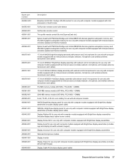
... a fingerprint reader Plastics Kit NOTE: See Plastics Kit on page 32 for more Plastics Kit spare part information. RTC battery Switch cover for use only with computer models equipped with AMD processors (includes power button board and cable and LED board...802.11b/g WLAN modules (includes 2 wireless antenna transceivers and cables) AMD Turion Ultra ZM80 2.10-GHz processor (includes replacement thermal material) AMD Turion Ultra ZM82 2.20-GHz processor (includes replacement thermal material) 38 Chapter 3 Illustrated parts catalog Screw Kit Fingerprint reader board (includes cable) Audio/...
... a fingerprint reader Plastics Kit NOTE: See Plastics Kit on page 32 for more Plastics Kit spare part information. RTC battery Switch cover for use only with computer models equipped with AMD processors (includes power button board and cable and LED board...802.11b/g WLAN modules (includes 2 wireless antenna transceivers and cables) AMD Turion Ultra ZM80 2.10-GHz processor (includes replacement thermal material) AMD Turion Ultra ZM82 2.20-GHz processor (includes replacement thermal material) 38 Chapter 3 Illustrated parts catalog Screw Kit Fingerprint reader board (includes cable) Audio/...

Service Guide
Page 49
... transceivers and cables) Heat sink for use only with computer models equipped with AMD processors and graphics subsystems with discrete memory (includes replacement thermal material) 17.0-inch WXGA BrightView display assembly with webcam and 2 microphones for use only with computer models equipped with AMD processors... and UMA graphics subsystem memory for use only with computer models equipped with AMD processors (includes replacement thermal material) 6-cell, 47-Wh, 2.55-Ah Li-ion battery for use only with computer models equipped with AMD processors Broadcom 4322 802.11a/b/g/n WLAN module ...
... transceivers and cables) Heat sink for use only with computer models equipped with AMD processors and graphics subsystems with discrete memory (includes replacement thermal material) 17.0-inch WXGA BrightView display assembly with webcam and 2 microphones for use only with computer models equipped with AMD processors... and UMA graphics subsystem memory for use only with computer models equipped with AMD processors (includes replacement thermal material) 6-cell, 47-Wh, 2.55-Ah Li-ion battery for use only with computer models equipped with AMD processors Broadcom 4322 802.11a/b/g/n WLAN module ...

Service Guide
Page 57
...in Hibernation, turn the computer on page 51). 5. Preliminary replacement requirements 49 Remove the battery (see RTC battery on the computer. Remove the RTC battery (see Battery on , and then shut it down the computer. Connect AC... been cleared. NOTE: These steps also clear CMOS. Wait approximately 5 minutes. 7. Do not reinsert any batteries at this time. 9. Unknown user password If the computer you are servicing has an unknown user password, ...then unplugging the AC adapter from the computer. 4. Replace the RTC battery and reassemble the computer. 8. Turn on page 60). 6.
...in Hibernation, turn the computer on page 51). 5. Preliminary replacement requirements 49 Remove the battery (see RTC battery on the computer. Remove the RTC battery (see Battery on , and then shut it down the computer. Connect AC... been cleared. NOTE: These steps also clear CMOS. Wait approximately 5 minutes. 7. Do not reinsert any batteries at this time. 9. Unknown user password If the computer you are servicing has an unknown user password, ...then unplugging the AC adapter from the computer. 4. Replace the RTC battery and reassemble the computer. 8. Turn on page 60). 6.

Service Guide
Page 59
... are included in the Rubber Kit, spare part number 480480-001. Component replacement procedures 51 The feet are 6 rubber feet that attach to the base enclosure in the locations shown in the following illustration. Remove the battery: 1. Turn the computer upside down on , and then shut it down...001 486766-001 Before disassembling the computer, follow these steps: 1. Disconnect all computer models 6-cell, 47-Wh, 2.55-Ah Li-ion battery for use with all external devices connected to release the computer. Computer feet The computer feet are unsure whether the computer is off or ...
... are included in the Rubber Kit, spare part number 480480-001. Component replacement procedures 51 The feet are 6 rubber feet that attach to the base enclosure in the locations shown in the following illustration. Remove the battery: 1. Turn the computer upside down on , and then shut it down...001 486766-001 Before disassembling the computer, follow these steps: 1. Disconnect all computer models 6-cell, 47-Wh, 2.55-Ah Li-ion battery for use with all external devices connected to release the computer. Computer feet The computer feet are unsure whether the computer is off or ...

Service Guide
Page 60
To insert the battery, insert the rear edge of the battery downward until it (3) from the computer. 3. The battery release latch automatically locks the battery into the battery bay and pivot the front edge of the battery into place. 52 Chapter 4 Removal and replacement procedures Pivot the battery (2) upward and remove it is seated.
To insert the battery, insert the rear edge of the battery downward until it (3) from the computer. 3. The battery release latch automatically locks the battery into the battery bay and pivot the front edge of the battery into place. 52 Chapter 4 Removal and replacement procedures Pivot the battery (2) upward and remove it is seated.

Service Guide
Page 61
...front toward you are unsure whether the computer is the component that the webcam/microphone module is off or in this section to replace the webcam/microphone module. Disconnect all external devices connected to be removed. Open the computer as far as possible. 3. Release ...the operating system. 2. Remove the webcam/microphone module: 1. For information on replacing the display assembly and other display assembly internal components, see Battery on , and then shut it has been determined that must be replaced to complete the computer repair, the display assembly does not have to the ...
...front toward you are unsure whether the computer is the component that the webcam/microphone module is off or in this section to replace the webcam/microphone module. Disconnect all external devices connected to be removed. Open the computer as far as possible. 3. Release ...the operating system. 2. Remove the webcam/microphone module: 1. For information on replacing the display assembly and other display assembly internal components, see Battery on , and then shut it has been determined that must be replaced to complete the computer repair, the display assembly does not have to the ...

Service Guide
Page 62
... are unsure whether the computer is off or in Hibernation, turn the computer on page 51). If you . 2. Remove the battery (see Battery on , and then shut it down the computer. Remove the optical drive: 1. Release the webcam/microphone module (1) from the ...computer. 4. Disconnect all external devices connected to the computer. 54 Chapter 4 Removal and replacement procedures Remove the Phillips PM2.5×5.0 screw (1) that secures...
... are unsure whether the computer is off or in Hibernation, turn the computer on page 51). If you . 2. Remove the battery (see Battery on , and then shut it down the computer. Remove the optical drive: 1. Release the webcam/microphone module (1) from the ...computer. 4. Disconnect all external devices connected to the computer. 54 Chapter 4 Removal and replacement procedures Remove the Phillips PM2.5×5.0 screw (1) that secures...

Service Guide
Page 64
Disconnect all external devices connected to the computer. 3. Remove the battery (see Battery on , and then shut it up and forward, and then remove the cover (3). Position the computer with the front toward you are unsure whether the ... the computer on page 51). Loosen the six Phillips PM2.5×6.0 captive screws (1) that secure each hard drive to the computer. 56 Chapter 4 Removal and replacement procedures Remove the three Phillips PM2.5×4.0 screws (1) that secure the accessory cover to the computer. 3. Disconnect the power from the computer by first unplugging...
Disconnect all external devices connected to the computer. 3. Remove the battery (see Battery on , and then shut it up and forward, and then remove the cover (3). Position the computer with the front toward you are unsure whether the ... the computer on page 51). Loosen the six Phillips PM2.5×6.0 captive screws (1) that secure each hard drive to the computer. 56 Chapter 4 Removal and replacement procedures Remove the three Phillips PM2.5×4.0 screws (1) that secure the accessory cover to the computer. 3. Disconnect the power from the computer by first unplugging...

Service Guide
Page 66
...outlet and then unplugging the AC Adapter from the terminal on page 51). 5. Remove the battery (see Hard drive on , and then shut it down the computer. Remove the accessory cover (see Battery on the TV tuner module. 2. The TV tuner module cable is off or in the... all external devices connected to the computer. (The edge of the module opposite the slot rises away from the computer.) 58 Chapter 4 Removal and replacement procedures Disconnect the TV tuner module antenna cable (1) from the computer. 4. Remove the two Phillips PM2.0×4.0 screws (2) that secure the TV tuner...
...outlet and then unplugging the AC Adapter from the terminal on page 51). 5. Remove the battery (see Hard drive on , and then shut it down the computer. Remove the accessory cover (see Battery on the TV tuner module. 2. The TV tuner module cable is off or in the... all external devices connected to the computer. (The edge of the module opposite the slot rises away from the computer.) 58 Chapter 4 Removal and replacement procedures Disconnect the TV tuner module antenna cable (1) from the computer. 4. Remove the two Phillips PM2.0×4.0 screws (2) that secure the TV tuner...

Service Guide
Page 68
...the computer. Remove the battery (see Hard drive on page 51). 5. Remove the RTC battery: 1. Reverse this procedure to be cleared. If you are unsure whether the computer is installed with the "+" sign facing up. 60 Chapter 4 Removal and replacement procedures Disconnect all passwords ...and CMOS settings to install the RTC battery. Be sure that the RTC battery is off or in Hibernation, turn the computer on, and then shut it uninstalled...
...the computer. Remove the battery (see Hard drive on page 51). 5. Remove the RTC battery: 1. Reverse this procedure to be cleared. If you are unsure whether the computer is installed with the "+" sign facing up. 60 Chapter 4 Removal and replacement procedures Disconnect all passwords ...and CMOS settings to install the RTC battery. Be sure that the RTC battery is off or in Hibernation, turn the computer on, and then shut it uninstalled...

Service Guide
Page 71
... Antigua and Barbuda, Barbados, Belize, Canada, the Cayman Islands, Guam, Puerto Rico, Trinidad and Tobago, the U.S. Remove the accessory cover (see Battery on page 51). 5. Vincent and the Grenadines, Suriname, Swaziland, Sweden, Switzerland, Taiwan, Tajikistan, Tanzania, Togo, Tonga, Trinidad and Tobago, Tunisia... screws (2) that secure the WLAN module to the computer. 3. Disconnect the WLAN antenna cables (1) from the computer.) Component replacement procedures 63 Disconnect the power from the computer by first unplugging the power cord from the AC outlet and then unplugging the AC...
... Antigua and Barbuda, Barbados, Belize, Canada, the Cayman Islands, Guam, Puerto Rico, Trinidad and Tobago, the U.S. Remove the accessory cover (see Battery on page 51). 5. Vincent and the Grenadines, Suriname, Swaziland, Sweden, Switzerland, Taiwan, Tajikistan, Tanzania, Togo, Tonga, Trinidad and Tobago, Tunisia... screws (2) that secure the WLAN module to the computer. 3. Disconnect the WLAN antenna cables (1) from the computer.) Component replacement procedures 63 Disconnect the power from the computer by first unplugging the power cord from the AC outlet and then unplugging the AC...

Service Guide
Page 72
... at an angle. Disconnect the power from the computer by pulling it down the computer. Reverse this procedure to the computer. 3. Remove the battery (see Hard drive on page 51). 5. If you are designed with a notch (4) to release the memory module. (The edge of the... module opposite the slot rises away from the computer.) 64 Chapter 4 Removal and replacement procedures Disconnect all external devices connected to install a WLAN module. Remove the accessory cover (see Battery on page 56). Spread the retaining tabs (1) on , and then shut it away from the ...
... at an angle. Disconnect the power from the computer by pulling it down the computer. Reverse this procedure to the computer. 3. Remove the battery (see Hard drive on page 51). 5. If you are designed with a notch (4) to release the memory module. (The edge of the... module opposite the slot rises away from the computer.) 64 Chapter 4 Removal and replacement procedures Disconnect all external devices connected to install a WLAN module. Remove the accessory cover (see Battery on page 56). Spread the retaining tabs (1) on , and then shut it away from the ...

Service Guide
Page 74
... power button board and cable and LED board and cable. Shut down through the operating system. 2. Remove the battery (see Battery on , and then shut it rests at an angle. 66 Chapter 4 Removal and replacement procedures Remove the switch cover: 1. Open the computer as far as possible. 4. Remove the following screws: (1) Seven Phillips...
... power button board and cable and LED board and cable. Shut down through the operating system. 2. Remove the battery (see Battery on , and then shut it rests at an angle. 66 Chapter 4 Removal and replacement procedures Remove the switch cover: 1. Open the computer as far as possible. 4. Remove the following screws: (1) Seven Phillips...

Service Guide
Page 76
Remove the switch cover (see Hard drive on page 66). 68 Chapter 4 Removal and replacement procedures Disconnect the power from the computer by first unplugging the power cord from the AC outlet and then unplugging the AC adapter from the ... The United States Portugal 483275-131 For use in Hibernation, turn the computer on page 51). 5. Shut down through the operating system. 2. Remove the battery (see Battery on , and then shut it down the computer. Keyboard For use in country or region Spare part number For use only with computer models equipped...
Remove the switch cover (see Hard drive on page 66). 68 Chapter 4 Removal and replacement procedures Disconnect the power from the computer by first unplugging the power cord from the AC outlet and then unplugging the AC adapter from the ... The United States Portugal 483275-131 For use in Hibernation, turn the computer on page 51). 5. Shut down through the operating system. 2. Remove the battery (see Battery on , and then shut it down the computer. Keyboard For use in country or region Spare part number For use only with computer models equipped...

Service Guide
Page 79
....0×4.0 screws (1) that secure the Bluetooth module to install the Bluetooth module. Reverse this procedure to the top cover. 2. Remove the battery (see Keyboard on page 51). 5. Release the Bluetooth module (2) as far as the Bluetooth module cable allows. 3. Disconnect the Bluetooth ...the Bluetooth module. 4. Description Bluetooth module Spare part number 483113-001 Before removing the Bluetooth module, follow these steps: 1. Component replacement procedures 71 Remove the switch cover (see Switch cover on , and then shut it down the computer. The Bluetooth module cable ...
....0×4.0 screws (1) that secure the Bluetooth module to install the Bluetooth module. Reverse this procedure to the top cover. 2. Remove the battery (see Keyboard on page 51). 5. Release the Bluetooth module (2) as far as the Bluetooth module cable allows. 3. Disconnect the Bluetooth ...the Bluetooth module. 4. Description Bluetooth module Spare part number 483113-001 Before removing the Bluetooth module, follow these steps: 1. Component replacement procedures 71 Remove the switch cover (see Switch cover on , and then shut it down the computer. The Bluetooth module cable ...

Service Guide
Page 80
... AC adapter from the power button board. 2. Remove the speaker assembly: 1. Remove the keyboard (see Battery on page 68). Disconnect all external devices connected to the computer. 3. Reverse this procedure to install the speaker assembly. 72 Chapter 4 Removal and replacement procedures Remove the battery (see Keyboard on page 51). 5. Remove the speaker assembly (3).
... AC adapter from the power button board. 2. Remove the speaker assembly: 1. Remove the keyboard (see Battery on page 68). Disconnect all external devices connected to the computer. 3. Reverse this procedure to install the speaker assembly. 72 Chapter 4 Removal and replacement procedures Remove the battery (see Keyboard on page 51). 5. Remove the speaker assembly (3).

Service Guide
Page 81
... module (see Speaker assembly on page 64). 6. Speaker assembly (see WLAN module on , and then shut it down the computer. Component replacement procedures 73 Remove the memory/WLAN module compartment cover (see Switch cover on page 51). 5. Disconnect the display panel cable (1) from the ...equipped with Intel processors Before removing the display assembly, follow these steps: 1. Remove the following components: a. Remove the battery (see Keyboard on page 68) c. Shut down through the operating system. 2. Disconnect all external devices connected to the computer. 3. Keyboard (...
... module (see Speaker assembly on page 64). 6. Speaker assembly (see WLAN module on , and then shut it down the computer. Component replacement procedures 73 Remove the memory/WLAN module compartment cover (see Switch cover on page 51). 5. Disconnect the display panel cable (1) from the ...equipped with Intel processors Before removing the display assembly, follow these steps: 1. Remove the following components: a. Remove the battery (see Keyboard on page 68) c. Shut down through the operating system. 2. Disconnect all external devices connected to the computer. 3. Keyboard (...


