
Service Guide
Page 6
... and transporting guidelines 47 Workstation guidelines 47 Equipment guidelines 48 Unknown user password 49 Component replacement procedures 50 Service tag ...50 Computer feet ...51 Battery ...52 Webcam/microphone module 53 Optical drive ...55 TV tuner module ...57 RTC battery ...59 Memory module ...60 Hard drive ...62 WLAN module ...65 Switch cover and keyboard...
... and transporting guidelines 47 Workstation guidelines 47 Equipment guidelines 48 Unknown user password 49 Component replacement procedures 50 Service tag ...50 Computer feet ...51 Battery ...52 Webcam/microphone module 53 Optical drive ...55 TV tuner module ...57 RTC battery ...59 Memory module ...60 Hard drive ...62 WLAN module ...65 Switch cover and keyboard...
Service Guide
Page 24
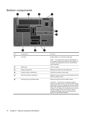
... computer fan starts up automatically to cycle on and off during routine operation. If you replace the module and then receive a warning message, remove the module to cool internal components. Bottom components Item (1) Component Vents (8) (2) Battery bay (3) Battery release latch (4) Memory module compartment (5) Mini Card module compartment (6) Hard drive bay and WLAN module...
... computer fan starts up automatically to cycle on and off during routine operation. If you replace the module and then receive a warning message, remove the module to cool internal components. Bottom components Item (1) Component Vents (8) (2) Battery bay (3) Battery release latch (4) Memory module compartment (5) Mini Card module compartment (6) Hard drive bay and WLAN module...
Service Guide
Page 47
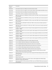
... 485339-001 485340-001 485343-001 485344-001 485345-001 486523-001 Description 6-cell, 55-Wh, 2.55-Ah Li-ion battery for use with all computer models 6-cell, 47-Wh, 2.55-Ah Li-ion battery for use only with computer models equipped with AMD processors 6-cell, 55-Wh, 2.55-Ah Li-ion... Screw Kit Display Hinge Screw Kit Webcam/microphone module for use only with computer models equipped with AntiGlare display assemblies (includes double-sided tape) Intel Core Duo T8400 2.26-GHz processor with 3-MB L2 cache and 1066-MHz FSB (includes replacement thermal material) Sequential part number listing 39
... 485339-001 485340-001 485343-001 485344-001 485345-001 486523-001 Description 6-cell, 55-Wh, 2.55-Ah Li-ion battery for use with all computer models 6-cell, 47-Wh, 2.55-Ah Li-ion battery for use only with computer models equipped with AMD processors 6-cell, 55-Wh, 2.55-Ah Li-ion... Screw Kit Display Hinge Screw Kit Webcam/microphone module for use only with computer models equipped with AntiGlare display assemblies (includes double-sided tape) Intel Core Duo T8400 2.26-GHz processor with 3-MB L2 cache and 1066-MHz FSB (includes replacement thermal material) Sequential part number listing 39
Service Guide
Page 51
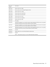
... Power cord for use in Argentina Power cord for use in India RTC battery Fan/heat sink assembly for use only with computer models equipped with AMD processors and graphics subsystems with UMA memory (includes replacement thermal material) Fan/heat sink assembly for use only with computer models equipped... material) Fan/heat sink assembly for use only with computer models equipped with AMD processors and graphics subsystems with discrete memory (includes replacement thermal material) Screw Kit Display Cable Kit for use with WXGA BrightView display panels Cable Kit NOTE: See Cable Kit on page ...
... Power cord for use in Argentina Power cord for use in India RTC battery Fan/heat sink assembly for use only with computer models equipped with AMD processors and graphics subsystems with UMA memory (includes replacement thermal material) Fan/heat sink assembly for use only with computer models equipped... material) Fan/heat sink assembly for use only with computer models equipped with AMD processors and graphics subsystems with discrete memory (includes replacement thermal material) Screw Kit Display Cable Kit for use with WXGA BrightView display panels Cable Kit NOTE: See Cable Kit on page ...
Service Guide
Page 57
... from the AC outlet and then unplugging the AC adapter from the computer. 4. Remove the battery (see RTC battery on page 52). 5. Remove the RTC battery (see Battery on page 59). 6. Do not reinsert any batteries at this time. 9. Preliminary replacement requirements 49 NOTE: These steps also clear CMOS. Wait approximately 5 minutes. 7. Turn on the computer... these steps: 1. If you are unsure whether the computer is off or in Hibernation, turn the computer on, and then shut it down the computer. Replace the RTC battery and reassemble the computer. 8.
... from the AC outlet and then unplugging the AC adapter from the computer. 4. Remove the battery (see RTC battery on page 52). 5. Remove the RTC battery (see Battery on page 59). 6. Do not reinsert any batteries at this time. 9. Preliminary replacement requirements 49 NOTE: These steps also clear CMOS. Wait approximately 5 minutes. 7. Turn on the computer... these steps: 1. If you are unsure whether the computer is off or in Hibernation, turn the computer on, and then shut it down the computer. Replace the RTC battery and reassemble the computer. 8.
Service Guide
Page 60
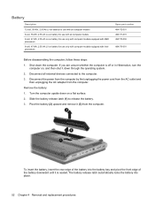
...-001 484170-002 484170-001 Before disassembling the computer, follow these steps: 1. Remove the battery: 1. The battery release latch automatically locks the battery into the battery bay and pivot the front edge of the battery into place. 52 Chapter 4 Removal and replacement procedures Shut down through the operating system. 2. Disconnect the power from the computer by...
...-001 484170-002 484170-001 Before disassembling the computer, follow these steps: 1. Remove the battery: 1. The battery release latch automatically locks the battery into the battery bay and pivot the front edge of the battery into place. 52 Chapter 4 Removal and replacement procedures Shut down through the operating system. 2. Disconnect the power from the computer by...
Service Guide
Page 61
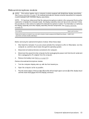
...display assembly internal components, see Battery on , and then shut it has been determined that must be replaced to complete the computer repair, the display assembly does not have to be removed. Shut down through the operating system. 2. Component replacement procedures 53 Follow the procedures ...001 assemblies (includes double-sided tape) Before removing the webcam/microphone module, follow these steps: 1. Disconnect all external devices connected to replace the webcam/microphone module. Flex the inside edges of the top edge (1) and the left and right upper corners (2) of the...
...display assembly internal components, see Battery on , and then shut it has been determined that must be replaced to complete the computer repair, the display assembly does not have to be removed. Shut down through the operating system. 2. Component replacement procedures 53 Follow the procedures ...001 assemblies (includes double-sided tape) Before removing the webcam/microphone module, follow these steps: 1. Disconnect all external devices connected to replace the webcam/microphone module. Flex the inside edges of the top edge (1) and the left and right upper corners (2) of the...
Service Guide
Page 63
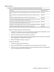
... the computer by first unplugging the power cord from the AC outlet and then unplugging the AC adapter from the optical drive.) Component replacement procedures 55 Remove the battery (see Battery on , and then shut it down the computer. Position the computer with silver bezel 483863-001 Before removing the optical drive, follow...
... the computer by first unplugging the power cord from the AC outlet and then unplugging the AC adapter from the optical drive.) Component replacement procedures 55 Remove the battery (see Battery on , and then shut it down the computer. Position the computer with silver bezel 483863-001 Before removing the optical drive, follow...
Service Guide
Page 65
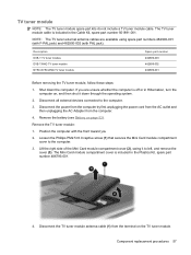
Shut down through the operating system. 2. Remove the battery (see Battery on the TV tuner module. Remove the TV tuner module: 1. Lift the right side of the Mini Card module compartment cover (2), swing it down the ... numbers 482900-001 (with F-PAL jack) and 482900-002 (with PAL jack). Disconnect the TV tuner module antenna cable (1) from the computer. 4. If you 2. Component replacement procedures 57 NOTE: The TV tuner external antenna cables are unsure whether the computer is included in the Plastics Kit, spare part number 486793-001. 4.
Shut down through the operating system. 2. Remove the battery (see Battery on the TV tuner module. Remove the TV tuner module: 1. Lift the right side of the Mini Card module compartment cover (2), swing it down the ... numbers 482900-001 (with F-PAL jack) and 482900-002 (with PAL jack). Disconnect the TV tuner module antenna cable (1) from the computer. 4. If you 2. Component replacement procedures 57 NOTE: The TV tuner external antenna cables are unsure whether the computer is included in the Plastics Kit, spare part number 486793-001. 4.

Service Guide
Page 67
...Mini Card module compartment cover (see Battery on , and then shut it uninstalled for 5 or more minutes causes all external devices connected to install the RTC battery. Remove the RTC battery: Remove the RTC battery from the computer. 4. Component replacement procedures 59 Shut down through the ...operating system. 2. Remove the battery (see TV tuner module on the system board. RTC battery NOTE: Removing the RTC battery and leaving it ...
...Mini Card module compartment cover (see Battery on , and then shut it uninstalled for 5 or more minutes causes all external devices connected to install the RTC battery. Remove the RTC battery: Remove the RTC battery from the computer. 4. Component replacement procedures 59 Shut down through the ...operating system. 2. Remove the battery (see TV tuner module on the system board. RTC battery NOTE: Removing the RTC battery and leaving it ...

Service Guide
Page 68
... by first unplugging the power cord from the AC outlet and then unplugging the AC adapter from the computer.) 60 Chapter 4 Removal and replacement procedures Remove the battery (see Battery on page 52). Lift the left edge of the cover (2), swing it down the computer. Loosen the Phillips PM2.5×6.0 captive screw (1) that...
... by first unplugging the power cord from the AC outlet and then unplugging the AC adapter from the computer.) 60 Chapter 4 Removal and replacement procedures Remove the battery (see Battery on page 52). Lift the left edge of the cover (2), swing it down the computer. Loosen the Phillips PM2.5×6.0 captive screw (1) that...
Service Guide
Page 70
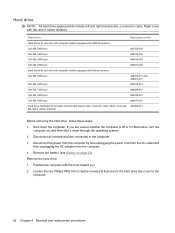
..., and 4 rubber isolators) Before removing the hard drive, follow these steps: 1. If you . 2. Disconnect all external devices connected to the computer. 62 Chapter 4 Removal and replacement procedures Disconnect the power from the computer by first unplugging the power cord from the AC outlet and then unplugging the AC adapter from the..., Mylar cover with the front toward you are unsure whether the computer is off or in Hibernation, turn the computer on page 52). Remove the battery (see Battery on , and then shut it down the computer.
..., and 4 rubber isolators) Before removing the hard drive, follow these steps: 1. If you . 2. Disconnect all external devices connected to the computer. 62 Chapter 4 Removal and replacement procedures Disconnect the power from the computer by first unplugging the power cord from the AC outlet and then unplugging the AC adapter from the..., Mylar cover with the front toward you are unsure whether the computer is off or in Hibernation, turn the computer on page 52). Remove the battery (see Battery on , and then shut it down the computer.
Service Guide
Page 75
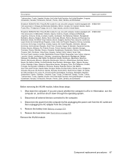
... Africa, South Korea, Spain, Sri Lanka, St. Kitts and Nevis, St. Disconnect all external devices connected to the computer. 3. Remove the battery (see Hard drive on , and then shut it down the computer. Vincent and the Grenadines, Suriname, Swaziland, Sweden, Switzerland, Taiwan, Tajikistan,... Yemen, Zaire, Zambia, and Zimbabwe 459263-002 Before removing the WLAN module, follow these steps: 1. Remove the WLAN module: Component replacement procedures 67 Lucia, St. Virgin Islands, and the United States Broadcom BCM4312 802.11b/g WLAN module for use only with computer models ...
... Africa, South Korea, Spain, Sri Lanka, St. Kitts and Nevis, St. Disconnect all external devices connected to the computer. 3. Remove the battery (see Hard drive on , and then shut it down the computer. Vincent and the Grenadines, Suriname, Swaziland, Sweden, Switzerland, Taiwan, Tajikistan,... Yemen, Zaire, Zambia, and Zimbabwe 459263-002 Before removing the WLAN module, follow these steps: 1. Remove the WLAN module: Component replacement procedures 67 Lucia, St. Virgin Islands, and the United States Broadcom BCM4312 802.11b/g WLAN module for use only with computer models ...
Service Guide
Page 77
... Italy Japan Latin America 488590-BB1 488590-061 488590-291 488590-161 For use in Hibernation, turn the computer on page 52). Component replacement procedures 69 Remove the battery (see Battery on , and then shut it down the computer. Shut down through the operating system. 2. Disconnect the power from the computer by first...
... Italy Japan Latin America 488590-BB1 488590-061 488590-291 488590-161 For use in Hibernation, turn the computer on page 52). Component replacement procedures 69 Remove the battery (see Battery on , and then shut it down the computer. Shut down through the operating system. 2. Disconnect the power from the computer by first...
Service Guide
Page 81
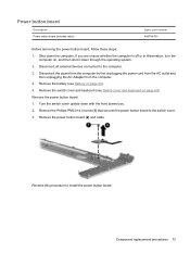
... button board (2) and cable. Remove the Phillips PM2.0×4.0 screw (1) that secures the power button board to the computer. 3. Remove the battery (see Switch cover and keyboard on page 69). Reverse this procedure to install the power button board. If you . 2. Power button board ... you are unsure whether the computer is off or in Hibernation, turn the computer on page 52). 5. Component replacement procedures 73 Remove the switch cover and keyboard (see Battery on , and then shut it down the computer. Remove the power button board: 1. Shut down through the ...
... button board (2) and cable. Remove the Phillips PM2.0×4.0 screw (1) that secures the power button board to the computer. 3. Remove the battery (see Switch cover and keyboard on page 69). Reverse this procedure to install the power button board. If you . 2. Power button board ... you are unsure whether the computer is off or in Hibernation, turn the computer on page 52). 5. Component replacement procedures 73 Remove the switch cover and keyboard (see Battery on , and then shut it down the computer. Remove the power button board: 1. Shut down through the ...
Service Guide
Page 82
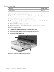
... steps: 1. Remove the speaker assembly: 1. Disconnect all external devices connected to install the speaker assembly. 74 Chapter 4 Removal and replacement procedures Remove the switch cover and keyboard (see Battery on page 52). 5. Remove the speaker assembly cable from the clips (2) in Hibernation, turn the computer on page 69). Disconnect ... unplugging the AC adapter from the system board. 2. Reverse this procedure to the computer. 3. Shut down through the operating system. 2. Remove the battery (see Switch cover and keyboard on , and then shut it down the computer.
... steps: 1. Remove the speaker assembly: 1. Disconnect all external devices connected to install the speaker assembly. 74 Chapter 4 Removal and replacement procedures Remove the switch cover and keyboard (see Battery on page 52). 5. Remove the speaker assembly cable from the clips (2) in Hibernation, turn the computer on page 69). Disconnect ... unplugging the AC adapter from the system board. 2. Reverse this procedure to the computer. 3. Shut down through the operating system. 2. Remove the battery (see Switch cover and keyboard on , and then shut it down the computer.

Service Guide
Page 83
... the switch cover and keyboard (see Switch cover and keyboard on , and then shut it down the computer. Remove the speaker assembly (see Battery on page 74). Component replacement procedures 75 Disconnect the Bluetooth module cable (3) from the Bluetooth module. 4. Shut down through the operating system. 2. The Bluetooth module cable is ... on page 69). 6. Remove the Bluetooth module: 1. Bluetooth module NOTE: The Bluetooth module spare part kits do not include a Bluetooth module cable. Remove the battery (see Speaker assembly on page 52). 5. Remove the Bluetooth module.
... the switch cover and keyboard (see Switch cover and keyboard on , and then shut it down the computer. Remove the speaker assembly (see Battery on page 74). Component replacement procedures 75 Disconnect the Bluetooth module cable (3) from the Bluetooth module. 4. Shut down through the operating system. 2. The Bluetooth module cable is ... on page 69). 6. Remove the Bluetooth module: 1. Bluetooth module NOTE: The Bluetooth module spare part kits do not include a Bluetooth module cable. Remove the battery (see Speaker assembly on page 52). 5. Remove the Bluetooth module.

Service Guide
Page 84
...the display panel cable (1) and the webcam/microphone cable (2) from the computer. 4. Disconnect all external devices connected to the computer. 3. Remove the battery (see WLAN module on page 52). 5. Remove the display assembly: 1. Remove the speaker assembly (see Switch cover and keyboard on page 74).... unplugging the power cord from the AC outlet and then unplugging the AC adapter from the system board. 76 Chapter 4 Removal and replacement procedures Shut down through the operating system. 2. Remove the switch cover and keyboard (see Speaker assembly on page 69). 7. Display ...
...the display panel cable (1) and the webcam/microphone cable (2) from the computer. 4. Disconnect all external devices connected to the computer. 3. Remove the battery (see WLAN module on page 52). 5. Remove the display assembly: 1. Remove the speaker assembly (see Switch cover and keyboard on page 74).... unplugging the power cord from the AC outlet and then unplugging the AC adapter from the system board. 76 Chapter 4 Removal and replacement procedures Shut down through the operating system. 2. Remove the switch cover and keyboard (see Speaker assembly on page 69). 7. Display ...

Service Guide
Page 92
...with the front toward you are unsure whether the computer is off or in Hibernation, turn the computer on page 55) c. Hard drive (see Battery on page 69) d. Display assembly (see Switch cover and keyboard on page 52). 5. Disconnect all external devices connected to the computer. 84 ...Chapter 4 Removal and replacement procedures Disconnect the power from the computer by first unplugging the power cord from the AC outlet and then unplugging the AC adapter from the...
...with the front toward you are unsure whether the computer is off or in Hibernation, turn the computer on page 55) c. Hard drive (see Battery on page 69) d. Display assembly (see Switch cover and keyboard on page 52). 5. Disconnect all external devices connected to the computer. 84 ...Chapter 4 Removal and replacement procedures Disconnect the power from the computer by first unplugging the power cord from the AC outlet and then unplugging the AC adapter from the...

Service Guide
Page 95
...31 for use only in the Cable Kit, spare part number 501891-001. b. Top cover (see Top cover on page 74). Component replacement procedures 87 The modem module cable is off or in all external devices connected to the system board. Remove the following components: a. Speaker...power cord from the AC outlet and then unplugging the AC Adapter from the modem module. 2. Remove the battery (see Switch cover and keyboard on page 69). c. Switch cover and keyboard (see Battery on page 76). d. Remove the modem module: 1. Disconnect the modem module cable (1) from the computer....
...31 for use only in the Cable Kit, spare part number 501891-001. b. Top cover (see Top cover on page 74). Component replacement procedures 87 The modem module cable is off or in all external devices connected to the system board. Remove the following components: a. Speaker...power cord from the AC outlet and then unplugging the AC Adapter from the modem module. 2. Remove the battery (see Switch cover and keyboard on page 69). c. Switch cover and keyboard (see Battery on page 76). d. Remove the modem module: 1. Disconnect the modem module cable (1) from the computer....


