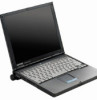
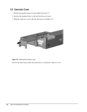
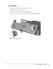
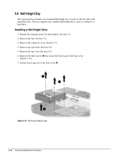
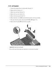
End User License Agreement
Page 2
... EULA will prevail. 4. Recovery Solution. The use technical information you provide in this EULA or if you must first be governed by HP as a consignment. Restrictions. CONSENT TO USE OF DATA. All intellectual property rights in this EULA. 5. You shall not remove any ... mandated under applicable law notwithstanding this EULA. 8. The transfer may not reverse engineer, decompile, or disassemble the Software Product, except and only to the extent that HP and its suppliers and are protected by law, including but not limited to comply with any product ...
Compaq ArmadaStation EM Maintenance and Service Guide
Page 4
Cables and Connectors ...4-7 Plastic Parts...4-7 chapter 5 EXPANSION BASE REMOVAL AND REPLACEMENT PROCEDURES 5.1 Serial Number ...5-1 5.2 Disassembly Sequence Chart...5-2 5.3 Preparing the Expansion Base for Disassembly 5-3 5.4 External Components...5-4 Expansion Base Feet...5-4 Tray ...5-5 5.5 Connector Cover ...5-6 5.6 Rear Bezel ...5-7 5.7 PCI Expansion Boards ...5-9 5.8 Top Cover...5-12 5.9 Half-Height Bay...5-14 Installing a Half-Height Drive...5-14 5....
Compaq ArmadaStation EM Maintenance and Service Guide
Page 29
...servicing the Compaq Expansion Base, ensure that all screws removed during reassembly can damage the unit. Using an improper screw during disassembly be placed away from the Compaq Expansion Base, it should keep in the Compaq Expansion Base are kept with the part with... supply and backplane removal procedures) s Phillips screwdriver (for bezel cage removal and installation procedures) Screws The screws used during the disassembly and assembly of the considerations that all screws are not interchangeable. Compaq strongly recommends that you should be kept with which they ...
Compaq ArmadaStation EM Maintenance and Service Guide
Page 30
.... Removal and Replacement Preliminaries 4-7 Handle flex cables with extreme care to avoid damage. Apply pressure only at the points designated in their proper location during disassembly and reassembly. they cannot be caught or snagged by the connector whenever possible. Apply only the tension required to separate plastic components. When handling the...
Compaq ArmadaStation EM Maintenance and Service Guide
Page 32
5.2 Disassembly Sequence Chart Use the chart below to determine the section number and disassembly sequence for removing components from the Compaq ArmadaStation EM. 5.3 Preparing the Expansion Base for Disassembly 5.4 External Components Expansion Base Feet Tray 5.5 Connector Cover 5.6 Rear Bezel 5.7 PCI Expansion Boards 5.8 Top Cover 5.9 Half-Height Bay 5.10 Left Speaker 5.11 MultiBay 5.12 Control Panel 5.13 Mechanism Assembly 5.14 Power Supply 5.15 Backplane Figure 5-2. Expansion Base Disassembly Sequence 5-2 Removal and Replacement Procedures
Compaq ArmadaStation EM Maintenance and Service Guide
Page 33
5.3 Preparing the Expansion Base for Disassembly 1. Turn the expansion base keylock counterclockwise to unlock it. 2. Disconnect any MultiBay devices from the expansion base . Undock the computer from the wall outlet (Figure 5-3). 5. Removal and Replacement Procedures 5-3 If installed, remove any external devices. 7. Turn off the expansion base. 4. Disconnecting the Expansion Base 6. Disconnect the power cord from the expansion base. 3. Disconnect the power cord from the expansion base MultiBays. Figure 5-3.
Compaq ArmadaStation EM Maintenance and Service Guide
Page 35
... the label and screw located behind the retaining latch (Figure 5-5). 4. Pull forward on the expansion base. Prepare the expansion base for disassembly (Section 5.3). 2. Removal and Replacement Procedures 5-5 Tray The tray is used to align the computer on the retaining latch to install the tray.
Compaq ArmadaStation EM Maintenance and Service Guide
Page 36
Figure 5-6. Position the expansion base so the rear bezel faces forward. 3. Prepare the expansion base for disassembly (Section 5.3). 2. Removing the Connector Cover Reverse the removal procedure described above to the left and remove it (Figure 5-6). Slide the connector cover to install the connector cover. 5-6 Removal and Replacement Procedures 5.5 Connector Cover 1.
Compaq ArmadaStation EM Maintenance and Service Guide
Page 37
Figure 5-7. Removing the Rear Bezel Removal and Replacement Procedures 5-7 Prepare the expansion base for disassembly (Section 5.3). 2. Remove the connector cover (Section 5.5). 3. Swing the bottom edge of the rear bezel forward and up until it disengages . Slide the rear bezel release latch to the left (Figure 5-7). 4. 5.6 Rear Bezel 1.
Compaq ArmadaStation EM Maintenance and Service Guide
Page 39
... board can be installed in slots , and ; Remove the connector cover (Section 5.5). 3. 5.7 PCI Expansion Boards The expansion base provides three slots for disassembly (Section 5.3). 2. Removal and Replacement Procedures 5-9 Prepare the expansion base for 32- Figure 5-9.
Compaq ArmadaStation EM Maintenance and Service Guide
Page 42
Figure 5-12. 5.8 Top Cover 1. Remove the tray (Section 5.4). 3. Prepare the expansion base for disassembly (Section 5.3). 2. Remove the five screws that secure the top cover to the base cover (Figure 5-12). Remove the connector cover (Section 5.5). 4. Removing the Top Cover Screws 5-12 Removal and Replacement Procedures Remove the rear bezel (Section 5.6). 5.
Compaq ArmadaStation EM Maintenance and Service Guide
Page 44
... Bay The expansion base features one standard half-height bay, located on the left side of the base cover . Prepare the expansion base for disassembly (Section 5.3). 2. Removing the Bezel Cage 5-14 Removal and Replacement Procedures Installing a Half-Height Drive 1. Remove the three screws that secure the bezel cage to...
Compaq ArmadaStation EM Maintenance and Service Guide
Page 53
... screws that secure the left speaker to install the left speaker. Removal and Replacement Procedures 5-23 5.10 Left Speaker 1. Prepare the expansion base for disassembly (Section 5.3). 2. Remove the left speaker cable from the base assembly. Removing the Left Speaker Reverse the removal procedure described above to the base assembly. 7. Remove...
Compaq ArmadaStation EM Maintenance and Service Guide
Page 54
... devices supported by the Compaq Armada Series of the expansion base. Figure 5-24. Remove the top cover (Section 5.8). 6. Remove the connector cover (Section 5.5). 4. Remove the rear bezel (Section 5.6). 5. Disconnecting the Half-Height Bay and Left Speaker Cables 5-24 Removal and Replacement Procedures Prepare the expansion base for disassembly (Section 5.3). 2. Disconnect the left...
Compaq ArmadaStation EM Maintenance and Service Guide
Page 56
... control panel to the MultiBay. 5-26 Removal and Replacement Procedures Remove the rear bezel (Section 5.6). 5. Remove the top cover (Section 5.8). 6. Prepare the expansion base for disassembly (Section 5.3). 2. Remove the connector cover (Section 5.5). 4. Remove the control panel from the MultiBay (Figure 5-26). 8. Figure 5-26. Remove the tray (Section 5.4). 3. Disconnect the right speaker...
Compaq ArmadaStation EM Maintenance and Service Guide
Page 57
... Assembly Screws Removal and Replacement Procedures 5-27 Remove the rear bezel (Section 5.6). 4. Figure 5-27. The mechanism assembly is used as a unit and should not be disassembled. 1. Remove the top cover (Section 5.8). 5. 5.13 Mechanism Assembly IMPORTANT: The mechanism assembly contains white lithium grease, which is spared as a lubricant. Disconnect the two mechanism...
Compaq ArmadaStation EM Maintenance and Service Guide
Page 59
... secure the power supply to the backplane . 6. Remove the rear bezel (Section 5.6). 4. Figure 5-29. Removal and Replacement Procedures 5-29 Prepare the expansion base for disassembly (Section 5.3). 2. Disconnect the power supply cable connected to the base cover (Figure 5-29). 5.14 Power Supply CAUTION: Do not handle or carry the power supply...
Compaq ArmadaStation EM Maintenance and Service Guide
Page 61
... the mechanism assembly (Section 5.13). 8. Figure 5-31. If installed, remove any PCI expansion boards (Section 5.7). 5. Remove the MultiBay (Section 5.11). 7. Prepare the expansion base for disassembly (Section 5.3). 2. Removing the Backplane Reverse the removal procedure described above to the base cover (Figure 5-31). 10. Remove the power supply (Section 5.14). 9. Remove the...
Compaq ArmadaStation EM Maintenance and Service Guide
Page 72
... panel, 1-5 right side, 1-4 spare part numbers, 3-3 top, 1-3 computer eject button illustrated, 1-4 connector cover illustrated, 3-2, 3-4 connectors, 4-7 control panel illustrated, 3-2 removing, 5-26 spare part number, 3-3 D depth specification, 6-1 disassembly sequence chart, 5-2 disconnecting power, 5-3 diskette drive, 1-3 cable connecting, 5-19 illustrated, 3-2, 3-5 docking connector illustrated, 1-3 pinout, A-4 drive power cable illustrated, 3-5 E electrostatic discharge, 4-1 preventing damage, 4-2 expansion board installing...
Compaq ArmadaStation EM Maintenance and Service Guide
Page 73
... 1-3 release button illustrated, 1-3 O operating current specification, 6-1 operating voltage specification, 6-1 P parallel connector illustrated, 1-5 pinout, A-2 PC Card inserting, 5-11 PCI card slots illustrated, 1-4 PCI CardBus Reader inserting, 5-11 spare part number, 3-6 PCI expansion board, ..., 3-2 removing, 5-29 spare part number, 3-3 supply cable disconnecting, 5-29 power/suspend light, 1-6 illustrated, 1-3 preparing for disassembly, 5-3 preventing damage to drives, 4-3 preventing electrostatic damage, 4-2 R rated current specification, 6-1 rated line frequency specification, 6-1 rated...