Owners Manual
Page 1
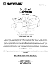
EcoStar is the industry's most energy efficient variable speed pump. The totally enclosed, permanent magnet motor combined with a Hayward or third party controller and features an easy-to avoid unnecessary service calls, read this manual carefully and completely. To prevent potential injury and to -use digital control interface that can be mounted in four different positions on...
EcoStar is the industry's most energy efficient variable speed pump. The totally enclosed, permanent magnet motor combined with a Hayward or third party controller and features an easy-to avoid unnecessary service calls, read this manual carefully and completely. To prevent potential injury and to -use digital control interface that can be mounted in four different positions on...

Owners Manual
Page 2
... 6.4. Timer Menu 22 6.8. Preset Speed Setup Menu 23 6.9. Shaft Seal Change Instructions ...26 Page 2 of pump speed) 16 5.5. Remote Control Wiring/Operation 11 4.11. General Information ...7 2.1. Introduction 7 2.2. Pump Location 8 4.2. Pump Mounting 8 4.3. Installation Procedure 14 5. Wiring Diagrams...14 5.1. External Relay Speed Control Wiring (For remote selection of 36 USE ONLY HAYWARD GENUINE REPLACEMENT PARTS EcoStar Variable Speed Pump IS3401VSP Rev-2 Startup & Operation ...17...
... 6.4. Timer Menu 22 6.8. Preset Speed Setup Menu 23 6.9. Shaft Seal Change Instructions ...26 Page 2 of pump speed) 16 5.5. Remote Control Wiring/Operation 11 4.11. General Information ...7 2.1. Introduction 7 2.2. Pump Location 8 4.2. Pump Mounting 8 4.3. Installation Procedure 14 5. Wiring Diagrams...14 5.1. External Relay Speed Control Wiring (For remote selection of 36 USE ONLY HAYWARD GENUINE REPLACEMENT PARTS EcoStar Variable Speed Pump IS3401VSP Rev-2 Startup & Operation ...17...
Owners Manual
Page 6
...pool and spa circulation system, all national, state, and local codes applicable. Installation of 36 USE ONLY HAYWARD GENUINE REPLACEMENT PARTS EcoStar Variable Speed Pump IS3401VSP Rev-2 Do not operate pool and spa circulation system unless filter manual air relief valve body is damaged, broken... defined instructions may cause severe personal injury or death. It is recommended. Failure to install according to follow all system and pump controls must be in severe personal injury and/or property damage. Page 6 of a vacuum release or vent system, which may ...
...pool and spa circulation system, all national, state, and local codes applicable. Installation of 36 USE ONLY HAYWARD GENUINE REPLACEMENT PARTS EcoStar Variable Speed Pump IS3401VSP Rev-2 Do not operate pool and spa circulation system unless filter manual air relief valve body is damaged, broken... defined instructions may cause severe personal injury or death. It is recommended. Failure to install according to follow all system and pump controls must be in severe personal injury and/or property damage. Page 6 of a vacuum release or vent system, which may ...
Owners Manual
Page 7
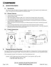
... 2.2. Energy Efficiency Overview The energy consumed by Hayward or third party pool and spa control platforms, without issue 2.3. Cost of electricity = $0.10 per kWh Convert Watts to 8 custom speed and timer functions For enhanced pool ...kW X $0.10/kWh = $0.03 per Hour Example: EcoStar Variable Speed Pump operating at 300 W. Product Dimensions 3. The EcoStar Variable Speed Pump displays power consumption in terms of Pump Operation per hour Page 7 of the Hayward EcoStar Variable Speed Pump. 2. Introduction This manual contains information for high temperatures and ...
... 2.2. Energy Efficiency Overview The energy consumed by Hayward or third party pool and spa control platforms, without issue 2.3. Cost of electricity = $0.10 per kWh Convert Watts to 8 custom speed and timer functions For enhanced pool ...kW X $0.10/kWh = $0.03 per Hour Example: EcoStar Variable Speed Pump operating at 300 W. Product Dimensions 3. The EcoStar Variable Speed Pump displays power consumption in terms of Pump Operation per hour Page 7 of the Hayward EcoStar Variable Speed Pump. 2. Introduction This manual contains information for high temperatures and ...
Owners Manual
Page 10
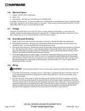
...used to power the equipment during a time cycle when the EcoStar pump is being used . Bonding reduces the risk of 36 USE ONLY HAYWARD GENUINE REPLACEMENT PARTS EcoStar Variable Speed Pump IS3401VSP Rev-2 Wiring WARNING - If the EcoStar pump is operating at an appropriate flow rate to operate the other ...or more than 110% of swimming pool, spa, or hot tub. 4.9. Use the circuit breaker as a heater, heat pump, or booster pump) that was controlled by code. from external bonding lug to add their amp loads before calculating wire and circuit breaker sizes. Bonding will connect ...
...used to power the equipment during a time cycle when the EcoStar pump is being used . Bonding reduces the risk of 36 USE ONLY HAYWARD GENUINE REPLACEMENT PARTS EcoStar Variable Speed Pump IS3401VSP Rev-2 Wiring WARNING - If the EcoStar pump is operating at an appropriate flow rate to operate the other ...or more than 110% of swimming pool, spa, or hot tub. 4.9. Use the circuit breaker as a heater, heat pump, or booster pump) that was controlled by code. from external bonding lug to add their amp loads before calculating wire and circuit breaker sizes. Bonding will connect ...
Owners Manual
Page 11
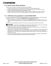
... of 36 USE ONLY HAYWARD GENUINE REPLACEMENT PARTS EcoStar Variable Speed Pump IS3401VSP Rev-2 EcoStar can operate by itself in Stand-Alone Mode using relay contacts. The presence of protection against body suction entrapment. Page 11 of Hayward controls. SVRS Notes (Only applicable...verify proper adjustment and operation of valves that could isolate the SVRS device from third party controls (i.e. See Section 5.4 for more information regarding connecting EcoStar and Hayward controls. 3. x 12 in the suction piping has been shown to site-specific hydraulic conditions...
... of 36 USE ONLY HAYWARD GENUINE REPLACEMENT PARTS EcoStar Variable Speed Pump IS3401VSP Rev-2 EcoStar can operate by itself in Stand-Alone Mode using relay contacts. The presence of protection against body suction entrapment. Page 11 of Hayward controls. SVRS Notes (Only applicable...verify proper adjustment and operation of valves that could isolate the SVRS device from third party controls (i.e. See Section 5.4 for more information regarding connecting EcoStar and Hayward controls. 3. x 12 in the suction piping has been shown to site-specific hydraulic conditions...
Owners Manual
Page 12
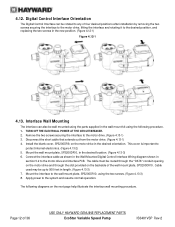
... 4.13-2) 5. This cover is important to the motor drive. (Figure 4.13-1) 3. The following procedure. 1. Digital Control Interface Orientation The Digital Control Interface can also be rotated to any of four desired positions after installation by removing the two screws securing the interface to... on the motor drive in the wall mount kit using the following diagrams on the backside of 36 USE ONLY HAYWARD GENUINE REPLACEMENT PARTS EcoStar Variable Speed Pump IS3401VSP Rev-2 Interface Wall Mounting The interface can be wall mounted using the two screws. (Figure 4.13-3) 8. ...
... 4.13-2) 5. This cover is important to the motor drive. (Figure 4.13-1) 3. The following procedure. 1. Digital Control Interface Orientation The Digital Control Interface can also be rotated to any of four desired positions after installation by removing the two screws securing the interface to... on the motor drive in the wall mount kit using the following diagrams on the backside of 36 USE ONLY HAYWARD GENUINE REPLACEMENT PARTS EcoStar Variable Speed Pump IS3401VSP Rev-2 Interface Wall Mounting The interface can be wall mounted using the two screws. (Figure 4.13-3) 8. ...

Owners Manual
Page 13
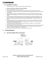
Figure 4.13-1: Removing the Digital Control Interface for Wall Mounting Figure 4.13-2: Adding the Blank Cover Figure 4.13-3: Wall Mounting the Interface Page 13 of 36 USE ONLY HAYWARD GENUINE REPLACEMENT PARTS EcoStar Variable Speed Pump IS3401VSP Rev-2
Figure 4.13-1: Removing the Digital Control Interface for Wall Mounting Figure 4.13-2: Adding the Blank Cover Figure 4.13-3: Wall Mounting the Interface Page 13 of 36 USE ONLY HAYWARD GENUINE REPLACEMENT PARTS EcoStar Variable Speed Pump IS3401VSP Rev-2
Owners Manual
Page 14
... on the outside of the drive enclosure. 8. If the pump will use the remote stop feature of 36 USE ONLY HAYWARD GENUINE REPLACEMENT PARTS EcoStar Variable Speed Pump IS3401VSP Rev-2 Wiring Diagrams 5.1. Remove the wiring access cover on the access cover. 9. If the installation will be controlled using 8AWG (6AWG for bonding is provided on the...
... on the outside of the drive enclosure. 8. If the pump will use the remote stop feature of 36 USE ONLY HAYWARD GENUINE REPLACEMENT PARTS EcoStar Variable Speed Pump IS3401VSP Rev-2 Wiring Diagrams 5.1. Remove the wiring access cover on the access cover. 9. If the installation will be controlled using 8AWG (6AWG for bonding is provided on the...
Owners Manual
Page 15
... wire must be up to the connectors. To determine Hayward control software revision, consult the appropriate Hayward pool control installation manual or visit our website at www.haywardpool.com. Use removable 6-position terminal block connectors for a minimum of 36 USE ONLY HAYWARD GENUINE REPLACEMENT PARTS EcoStar Variable Speed Pump IS3401VSP Rev-2 Page 15 of 300V, and may be...
... wire must be up to the connectors. To determine Hayward control software revision, consult the appropriate Hayward pool control installation manual or visit our website at www.haywardpool.com. Use removable 6-position terminal block connectors for a minimum of 36 USE ONLY HAYWARD GENUINE REPLACEMENT PARTS EcoStar Variable Speed Pump IS3401VSP Rev-2 Page 15 of 300V, and may be...
Owners Manual
Page 16
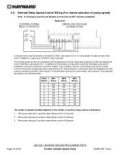
... Relay Speed Control Wiring (For remote selection of 36 USE ONLY HAYWARD GENUINE REPLACEMENT PARTS EcoStar Variable Speed Pump IS3401VSP Rev-2 Do not connect to the lower "COMBUS" or wall mount "DISPLAY" data terminals. Filter pump relay plus 3 auxiliary relays allows control of 8 speeds Page 16 of pump speed) Note: For third party controls and Hayward controls that are disabled when the pump is remotely controlled.
... Relay Speed Control Wiring (For remote selection of 36 USE ONLY HAYWARD GENUINE REPLACEMENT PARTS EcoStar Variable Speed Pump IS3401VSP Rev-2 Do not connect to the lower "COMBUS" or wall mount "DISPLAY" data terminals. Filter pump relay plus 3 auxiliary relays allows control of 8 speeds Page 16 of pump speed) Note: For third party controls and Hayward controls that are disabled when the pump is remotely controlled.
Owners Manual
Page 19
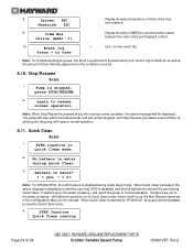
...(where "X" equals 1 through 8) d. Drive Serial Number b. The < and > arrow buttons are out of 36 USE ONLY HAYWARD GENUINE REPLACEMENT PARTS EcoStar Variable Speed Pump IS3401VSP Rev-2 The TIMERS ACTIVE LED will blink indicating that all bathers are used to edit, and the + and - The LED...will illuminate when the pump is active, and the CHECK SYSTEM LED will illuminate once timers have been programmed to prevent nuisance tripping during this button is used to stop the pump to program the 4 preset speeds) a. Remote Control Mode g. Low Temp Speed k. Pump Speed for Timer "X" (...
...(where "X" equals 1 through 8) d. Drive Serial Number b. The < and > arrow buttons are out of 36 USE ONLY HAYWARD GENUINE REPLACEMENT PARTS EcoStar Variable Speed Pump IS3401VSP Rev-2 The TIMERS ACTIVE LED will blink indicating that all bathers are used to edit, and the + and - The LED...will illuminate when the pump is active, and the CHECK SYSTEM LED will illuminate once timers have been programmed to prevent nuisance tripping during this button is used to stop the pump to program the 4 preset speeds) a. Remote Control Mode g. Low Temp Speed k. Pump Speed for Timer "X" (...
Owners Manual
Page 21
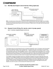
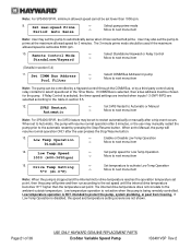
...5 minutes, or the user may be set to protect the pump, system plumbing, or pool from freezing. Set pump speed for pump Pool Filter Move to next menu item Note: The pump can be controlled by a Hayward control through the COMM Bus, or by pressing the Stop/Resume button... Set temperature to activate Low Temp Operation Move to the table in the Timer Menu. Remote Control Mode Standalone/Hayward +- Set COMM Bus Address +- Drive Temp Setting 5ºC (41.0ºF) +- Page 21 of 36 USE ONLY HAYWARD GENUINE REPLACEMENT PARTS EcoStar Variable Speed Pump IS3401VSP Rev-2
...5 minutes, or the user may be set to protect the pump, system plumbing, or pool from freezing. Set pump speed for pump Pool Filter Move to next menu item Note: The pump can be controlled by a Hayward control through the COMM Bus, or by pressing the Stop/Resume button... Set temperature to activate Low Temp Operation Move to the table in the Timer Menu. Remote Control Mode Standalone/Hayward +- Set COMM Bus Address +- Drive Temp Setting 5ºC (41.0ºF) +- Page 21 of 36 USE ONLY HAYWARD GENUINE REPLACEMENT PARTS EcoStar Variable Speed Pump IS3401VSP Rev-2
Owners Manual
Page 24
...will immediately proceed to Quick Clean mode. 4. Driver: 38C Heatsink: 32C Display showing temperature of 36 USE ONLY HAYWARD GENUINE REPLACEMENT PARTS EcoStar Variable Speed Pump IS3401VSP Rev-2 Use + to resume normal operation. When Quick Clean is disabled during Quick Clean. Note: When ... mode, where it will return the pump to view +- SVRS inactive in the water, pressing - Event log Press + to normal operation. Comm Bus Online (Addr: 1) Display showing COMM Bus communication status between the motor drive and Hayward control. 10. Stop/Resume Screen 1. 8....
...will immediately proceed to Quick Clean mode. 4. Driver: 38C Heatsink: 32C Display showing temperature of 36 USE ONLY HAYWARD GENUINE REPLACEMENT PARTS EcoStar Variable Speed Pump IS3401VSP Rev-2 Use + to resume normal operation. When Quick Clean is disabled during Quick Clean. Note: When ... mode, where it will return the pump to view +- SVRS inactive in the water, pressing - Event log Press + to normal operation. Comm Bus Online (Addr: 1) Display showing COMM Bus communication status between the motor drive and Hayward control. 10. Stop/Resume Screen 1. 8....
Owners Manual
Page 30
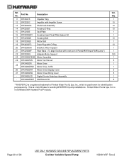
... & Spa, Inc., which is used herein for existing WHISPERFLO pump installations. This is not affiliated with inlet port of 36 USE ONLY HAYWARD GENUINE REPLACEMENT PARTS EcoStar Variable Speed Pump IS3401VSP Rev-2 is a retrofit base for identification purposes only. Page...pump*) 1 22 SPX3200Q Adapter-Motor Support 100 23 SPX3400Z1ECM Motor Assembly 1 24 SPX3400FAN Motor Fan Shroud 5 SPX3400DR Motor Drive 1 25 SPX3400DRVR Motor Drive, SVRS 1 26 SPX3400DR4 Motor Drive Display Cover 5 27 SPX3400DR2 Motor Drive Wiring Cover 5 - Part No. SPX3400LCD Digital Control...
... & Spa, Inc., which is used herein for existing WHISPERFLO pump installations. This is not affiliated with inlet port of 36 USE ONLY HAYWARD GENUINE REPLACEMENT PARTS EcoStar Variable Speed Pump IS3401VSP Rev-2 is a retrofit base for identification purposes only. Page...pump*) 1 22 SPX3200Q Adapter-Motor Support 100 23 SPX3400Z1ECM Motor Assembly 1 24 SPX3400FAN Motor Fan Shroud 5 SPX3400DR Motor Drive 1 25 SPX3400DRVR Motor Drive, SVRS 1 26 SPX3400DR4 Motor Drive Display Cover 5 27 SPX3400DR2 Motor Drive Wiring Cover 5 - Part No. SPX3400LCD Digital Control...
Owners Manual
Page 33
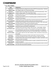
...not able to be replaced. Motor connections to be verified. Indicates that the drive has lost control over motor shaft rotation, or that the internal components of pump rated voltage. AC voltage too high Drive Error! Heatsink overheated Drive Error! Check impeller, diffuser... Verify that the input current limiter is within 15 minutes of 36 USE ONLY HAYWARD GENUINE REPLACEMENT PARTS EcoStar Variable Speed Pump IS3401VSP Rev-2 PFC Circuit Hi Drive Error! Indicates that the pump was disconnected and reconnected too quickly, and that line voltage is resetting itself. 11...
...not able to be replaced. Motor connections to be verified. Indicates that the drive has lost control over motor shaft rotation, or that the internal components of pump rated voltage. AC voltage too high Drive Error! Heatsink overheated Drive Error! Check impeller, diffuser... Verify that the input current limiter is within 15 minutes of 36 USE ONLY HAYWARD GENUINE REPLACEMENT PARTS EcoStar Variable Speed Pump IS3401VSP Rev-2 PFC Circuit Hi Drive Error! Indicates that the pump was disconnected and reconnected too quickly, and that line voltage is resetting itself. 11...
Technical Guide
Page 6
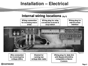
Electrical Internal wiring locations (fig 5) Wiring connection for incoming motor wires Wiring plug for relay connected controls & stop switch Wiring plug for wall mounted interface Wire connection for incoming line voltage (230v) Channel for running low voltage data cable Wiring plug for data link with Hayward/Goldline compatible software Controls Figure 5 Page 4 Installation -
Electrical Internal wiring locations (fig 5) Wiring connection for incoming motor wires Wiring plug for relay connected controls & stop switch Wiring plug for wall mounted interface Wire connection for incoming line voltage (230v) Channel for running low voltage data cable Wiring plug for data link with Hayward/Goldline compatible software Controls Figure 5 Page 4 Installation -

Technical Guide
Page 7
...that is both bonded and grounded Page 5 Figure 6 Conduit Connections There are two on the pump. Make sure the unit is data connected to a Hayward/Goldline control, voltage needs to come directly from a breaker in the control, or in the case of an OnCommand, directly from the main or sub-panel and ...not from the filter pump relay. Voltage: 230 VAC, 60Hz, Single Phase. 2. Bonding Lug 8 AWG (6 AWG ...
...that is both bonded and grounded Page 5 Figure 6 Conduit Connections There are two on the pump. Make sure the unit is data connected to a Hayward/Goldline control, voltage needs to come directly from a breaker in the control, or in the case of an OnCommand, directly from the main or sub-panel and ...not from the filter pump relay. Voltage: 230 VAC, 60Hz, Single Phase. 2. Bonding Lug 8 AWG (6 AWG ...

Technical Guide
Page 9
Installation-Interface /Wall mount 1. Plug is included with the EcoStar and includes blank cover, mounting bracket and new terminal block for wall mount or control connection. 2. Wall mount kit is permanently attached (fig 13), install the blank cover over the plug (fig 14). Maximum 500‟ for data cable used for connecting to the interface (fig 12). 3. Figure 12 Figure 13 Figure 14 Page 7 After removal of the interface assembly (Page 7) remove the plug connecting the drive to the interface assembly.
Installation-Interface /Wall mount 1. Plug is included with the EcoStar and includes blank cover, mounting bracket and new terminal block for wall mount or control connection. 2. Wall mount kit is permanently attached (fig 13), install the blank cover over the plug (fig 14). Maximum 500‟ for data cable used for connecting to the interface (fig 12). 3. Figure 12 Figure 13 Figure 14 Page 7 After removal of the interface assembly (Page 7) remove the plug connecting the drive to the interface assembly.

Technical Guide
Page 12
... necessary to come directly from a breaker in the control, or in units 8 Mfg 5/19/11 1 going forward Figure 23 Pump Terminal Data Plugs Page 10 Wire 7 on the pump to 2 on the controller, 8 on the pump to 3 on the controller and 1 on 7 EcoStar is data connected to a Hayward/Goldline control, voltage needs to operate the EcoStar Aqua Logic...
... necessary to come directly from a breaker in the control, or in units 8 Mfg 5/19/11 1 going forward Figure 23 Pump Terminal Data Plugs Page 10 Wire 7 on the pump to 2 on the controller, 8 on the pump to 3 on the controller and 1 on 7 EcoStar is data connected to a Hayward/Goldline control, voltage needs to operate the EcoStar Aqua Logic...

