
User Manual
Page 3
... system prior to the owner and explain its provisions. C: Air conditioner; H: Haier R System type - D=13, E=14 2 Design series. 2 - 2nd Generation V Electric: V=208/230-1-60; TABLE OF CONTENT 1.Introduction 1 2.Nomenclature for your new Heat Pump. Give this manual to installation. General 5 6.2.Unit clearances 6 6.3.Refrigerant piping ... 2 4.Unit Inspection 5 5.Equipment Protection From Environment 5 6.Installation 5 6.1. Improper installation can result in (000) Btu/h D SEER designation. R: Heat pump. 24 Nominal capacity in unsatisfactory operation or dangerous conditions.
... system prior to the owner and explain its provisions. C: Air conditioner; H: Haier R System type - D=13, E=14 2 Design series. 2 - 2nd Generation V Electric: V=208/230-1-60; TABLE OF CONTENT 1.Introduction 1 2.Nomenclature for your new Heat Pump. Give this manual to installation. General 5 6.2.Unit clearances 6 6.3.Refrigerant piping ... 2 4.Unit Inspection 5 5.Equipment Protection From Environment 5 6.Installation 5 6.1. Improper installation can result in (000) Btu/h D SEER designation. R: Heat pump. 24 Nominal capacity in unsatisfactory operation or dangerous conditions.
User Manual
Page 4
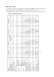
...2 MODEL: Unit Supply Voltage Normal Voltage Range Minimum Circuit Amps Max Fuse or Max CKT. The Figure 2 show a schematic of a heat pump on the cooling cycle and the heating cycle. Lbs (kg) Approx Shipping Weight - In (mm) R-22 Charge -Oz (g) Net Dimensions - Lbs (kg) HR18D2VAR 7.6 ...1.4 1/4 1075 3/8"[9.52] 3/4"[19.05] 141.34[4000] 24 1/4"*24 1/4"*26 7/8" [ 616 *616*683] 26 7/8"*26 7/8"*28 1/2" [682* 682*725] 189[86] 205[93] HR36D2VAR 16.4 3 0 11.8 78 1.6 1/3 1120 3/8"[9.52] 7/8"[22.2] 148.41[4200] 24 1/4"*24 1/4"*30 3/8" [616*616*771] 26 7/8"*26 7/8"*32" [682*682*813] 207[94...
...2 MODEL: Unit Supply Voltage Normal Voltage Range Minimum Circuit Amps Max Fuse or Max CKT. The Figure 2 show a schematic of a heat pump on the cooling cycle and the heating cycle. Lbs (kg) Approx Shipping Weight - In (mm) R-22 Charge -Oz (g) Net Dimensions - Lbs (kg) HR18D2VAR 7.6 ...1.4 1/4 1075 3/8"[9.52] 3/4"[19.05] 141.34[4000] 24 1/4"*24 1/4"*26 7/8" [ 616 *616*683] 26 7/8"*26 7/8"*28 1/2" [682* 682*725] 189[86] 205[93] HR36D2VAR 16.4 3 0 11.8 78 1.6 1/3 1120 3/8"[9.52] 7/8"[22.2] 148.41[4200] 24 1/4"*24 1/4"*30 3/8" [616*616*771] 26 7/8"*26 7/8"*32" [682*682*813] 207[94...
User Manual
Page 6
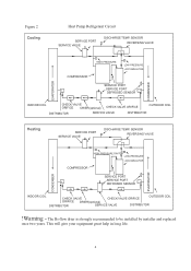
The Bi-flow drier is strongly recommended to be installed by installer and replaced once two years. Figure 2 Cooling Heat Pump Refrigerant Circuit SERVICE PORT SERVICE VALVE DISCHARGE TEMP. This will give your equipment great help in long life. 4... PORT DEFROSED SENSOR CONDENSER EVAPORATOR INDOOR COIL CHECK VALVE ORIFICE DRIER(optional) CHECK VALVE ORIFICE DISTRIBUTOR SERVICE VALVE DISTRIBUTOR OUTDOOR COIL Heating SERVICE PORT SERVICE VALVE DISCHARGE TEMP. SENSOR REVERSING VALVE COMPRESSOR HIGH PRESSURE SWITCH LOW PRESSURE ACCUMULATOR SERVICE PORT SERVICE PORT DEFROSED ...
The Bi-flow drier is strongly recommended to be installed by installer and replaced once two years. Figure 2 Cooling Heat Pump Refrigerant Circuit SERVICE PORT SERVICE VALVE DISCHARGE TEMP. This will give your equipment great help in long life. 4... PORT DEFROSED SENSOR CONDENSER EVAPORATOR INDOOR COIL CHECK VALVE ORIFICE DRIER(optional) CHECK VALVE ORIFICE DISTRIBUTOR SERVICE VALVE DISTRIBUTOR OUTDOOR COIL Heating SERVICE PORT SERVICE VALVE DISCHARGE TEMP. SENSOR REVERSING VALVE COMPRESSOR HIGH PRESSURE SWITCH LOW PRESSURE ACCUMULATOR SERVICE PORT SERVICE PORT DEFROSED ...

User Manual
Page 10
... the indoor unit is below the outdoor unit, suction line oil trap should be used as there is in Figure 4-A and Figure 4-B. Heat Pumps are as follows: 1/4" Line +/- 0.3 oz. CAUTION - Heat Pump liquid and suction valves are illustrated in the accessory bag. CAUTION - Tubing Connections ! Vertical Separation between Indoor and Outdoor Units Maximum allowable...
... the indoor unit is below the outdoor unit, suction line oil trap should be used as there is in Figure 4-A and Figure 4-B. Heat Pumps are as follows: 1/4" Line +/- 0.3 oz. CAUTION - Heat Pump liquid and suction valves are illustrated in the accessory bag. CAUTION - Tubing Connections ! Vertical Separation between Indoor and Outdoor Units Maximum allowable...


