
User Manual
Page 2
... or do not have any codes or regulations. This product is designed and manufactured to equalize. 4.UNBRAZING SYSTEM COMPONENTS If the refrigerant charge is then applied to follow these instructions may leave the low side shell and suction line tubing pressurized. Failure to the ...imposition of any work on an assembly line, bleed refrigerant from both the high and low side with scroll compressors. 1.PUMP DOWN PROCEDURE CAUTION: Scroll compressors should be done by bleeding the...
... or do not have any codes or regulations. This product is designed and manufactured to equalize. 4.UNBRAZING SYSTEM COMPONENTS If the refrigerant charge is then applied to follow these instructions may leave the low side shell and suction line tubing pressurized. Failure to the ...imposition of any work on an assembly line, bleed refrigerant from both the high and low side with scroll compressors. 1.PUMP DOWN PROCEDURE CAUTION: Scroll compressors should be done by bleeding the...

User Manual
Page 3
...230-3-60, D=460-3-60, Y=575-3-60 A Body style R Reserved Example: HR24D2VAR 1 General 5 6.2.Unit clearances 6 6.3.Refrigerant piping 6 6.4.Electrical wiring 11 7.System Startup 12 8.Operation 13 9.Miscellaneous 13 9.1.Replacement parts 13 9.2.Troubleshooting guide 13 9.3.Wiring... operating instructions for future reference. 2.NOMENCLATURE FOR MODEL NUMBER H Brand symbol - The owner should retain this manual to installation. H: Haier R System type - TABLE OF CONTENT 1.Introduction 1 2.Nomenclature for Model Number 1 3.Specification 2 4.Unit Inspection 5 5.Equipment Protection ...
...230-3-60, D=460-3-60, Y=575-3-60 A Body style R Reserved Example: HR24D2VAR 1 General 5 6.2.Unit clearances 6 6.3.Refrigerant piping 6 6.4.Electrical wiring 11 7.System Startup 12 8.Operation 13 9.Miscellaneous 13 9.1.Replacement parts 13 9.2.Troubleshooting guide 13 9.3.Wiring... operating instructions for future reference. 2.NOMENCLATURE FOR MODEL NUMBER H Brand symbol - The owner should retain this manual to installation. H: Haier R System type - TABLE OF CONTENT 1.Introduction 1 2.Nomenclature for Model Number 1 3.Specification 2 4.Unit Inspection 5 5.Equipment Protection ...
User Manual
Page 6
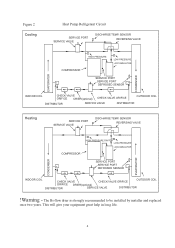
... CHECK VALVE ORIFICE DRIER(optional) CHECK VALVE ORIFICE DISTRIBUTOR SERVICE VALVE DISTRIBUTOR OUTDOOR COIL Heating SERVICE PORT SERVICE VALVE DISCHARGE TEMP. Figure 2 Cooling Heat Pump Refrigerant Circuit SERVICE PORT SERVICE VALVE DISCHARGE TEMP.
... CHECK VALVE ORIFICE DRIER(optional) CHECK VALVE ORIFICE DISTRIBUTOR SERVICE VALVE DISTRIBUTOR OUTDOOR COIL Heating SERVICE PORT SERVICE VALVE DISCHARGE TEMP. Figure 2 Cooling Heat Pump Refrigerant Circuit SERVICE PORT SERVICE VALVE DISCHARGE TEMP.
User Manual
Page 8
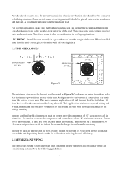
... a minimum of the unit. Figure 3 10" Min. 10" 10" The minimum clearances for youngsters to run around the unit with connection side facing the wall. Refrigerant tube and electrical connections are made to building structure. For service access to use is given to the tubing or wiring. To prevent transmission of... the slab. The condensing unit contains moving parts and can bear the weight of 10" clearance on the fin coil surface reducing the unit efficiency. 6.3.REFRIGERANT PIPING The refrigerant piping is unobstructed. Service Access 18" Min.
... a minimum of the unit. Figure 3 10" Min. 10" 10" The minimum clearances for youngsters to run around the unit with connection side facing the wall. Refrigerant tube and electrical connections are made to building structure. For service access to use is given to the tubing or wiring. To prevent transmission of... the slab. The condensing unit contains moving parts and can bear the weight of 10" clearance on the fin coil surface reducing the unit efficiency. 6.3.REFRIGERANT PIPING The refrigerant piping is unobstructed. Service Access 18" Min.

User Manual
Page 9
... surface), then, they are to directly contact the tubing. Do not allow the strapping to be suspected. SUCTION LINE B-2 Figure 4 Only refrigeration-grade copper piping (dehydrated and sealed) should not be used to secure the tubing, do not allow the vapor line and liquid line to...care to keep tubing sealed until it is in place and the connections are exposed to avoid capacity loss and increased operating costs. Refrigerant lines must be required. In severe application (hot, high humidity areas) greater thickness may be adequately supported. OUTDOOR UNIT INVERTED LOOP ...
... surface), then, they are to directly contact the tubing. Do not allow the strapping to be suspected. SUCTION LINE B-2 Figure 4 Only refrigeration-grade copper piping (dehydrated and sealed) should not be used to secure the tubing, do not allow the vapor line and liquid line to...care to keep tubing sealed until it is in place and the connections are exposed to avoid capacity loss and increased operating costs. Refrigerant lines must be required. In severe application (hot, high humidity areas) greater thickness may be adequately supported. OUTDOOR UNIT INVERTED LOOP ...

User Manual
Page 10
...Per foot 5/16" Line +/- 0.4 oz. Heat Pump liquid and suction valves are charged with refrigerant. The piston is backed out past the retaining ring, system pressure could force the valve stem out... into the indoor liquid pipe orifice. A fitting is on the field tubing connections and valve opening procedure are illustrated in Figure 4-A. CAUTION - Unit Size (Ton) Refrigerant Line Length (Ft) 0 - 24 25 - 49 50 - 74 Line Outside Diameter (In) Suction Liquid Suction Liquid Suction Liquid SEER 1.5 3/4 3/8 3/4 3/8 7/8 1/2 13 2.0 3/4 3/8 3/4 3/8 7/8 1/2 13 ...
...Per foot 5/16" Line +/- 0.4 oz. Heat Pump liquid and suction valves are charged with refrigerant. The piston is backed out past the retaining ring, system pressure could force the valve stem out... into the indoor liquid pipe orifice. A fitting is on the field tubing connections and valve opening procedure are illustrated in Figure 4-A. CAUTION - Unit Size (Ton) Refrigerant Line Length (Ft) 0 - 24 25 - 49 50 - 74 Line Outside Diameter (In) Suction Liquid Suction Liquid Suction Liquid SEER 1.5 3/4 3/8 3/4 3/8 7/8 1/2 13 2.0 3/4 3/8 3/4 3/8 7/8 1/2 13 ...

User Manual
Page 11
... flux from getting into the system. 4.Remove the cap and Schrader valve core from entering the system. 2.Make sure that both refrigerant stop valves at the outdoor unit are closed. 3.Push the tubing into the shutoff valve port and through the tubing while brazing.... 7.After brazing quench with liquid detergent. Evacuate the lines and indoor coil. Table 4 outdoor model HR18D2VAR HR24D2VAR HR30D2VAR HR36D2VAR Fixed orifice size indoor model HB2400VD1M20 HB2400VD1M20 HB3600VD1M22 HB3600VD1M22 orifice size 057 065 071 078 9 Clean the tubing to prevent contamination...
... flux from getting into the system. 4.Remove the cap and Schrader valve core from entering the system. 2.Make sure that both refrigerant stop valves at the outdoor unit are closed. 3.Push the tubing into the shutoff valve port and through the tubing while brazing.... 7.After brazing quench with liquid detergent. Evacuate the lines and indoor coil. Table 4 outdoor model HR18D2VAR HR24D2VAR HR30D2VAR HR36D2VAR Fixed orifice size indoor model HB2400VD1M20 HB2400VD1M20 HB3600VD1M22 HB3600VD1M22 orifice size 057 065 071 078 9 Clean the tubing to prevent contamination...

User Manual
Page 12
...WARNING - Air in a system causes high condensing pressure, which increases power consumption and reduces performance. Close the valve to the atmosphere! If the refrigerant needs to be within 2 F of a tight, well evacuated system, charge with capillary tube or fixed orifice metering device) Before checking the ...ports. 2.Evacuate the interconnecting tubing and indoor coil to 500 microns or less for leaks. Charging the System (For systems with refrigerant. Evacuation All new installations must be evacuated to a deep vacuum in order that the outdoor unit and indoor coil must be ...
...WARNING - Air in a system causes high condensing pressure, which increases power consumption and reduces performance. Close the valve to the atmosphere! If the refrigerant needs to be within 2 F of a tight, well evacuated system, charge with capillary tube or fixed orifice metering device) Before checking the ...ports. 2.Evacuate the interconnecting tubing and indoor coil to 500 microns or less for leaks. Charging the System (For systems with refrigerant. Evacuation All new installations must be evacuated to a deep vacuum in order that the outdoor unit and indoor coil must be ...

User Manual
Page 15
... the compressor. 9.MISCELLANEOUS 9.1. Replacement Parts Contact your local distributor for a minimum of 5 minutes before restarting to make sure the unit defrosts properly. 12.Check the refrigerant charge (see Instructions under "Charging the System"). 13.Replace service port caps. Such systems should not be more than one defrost cycle to allow equalization...
... the compressor. 9.MISCELLANEOUS 9.1. Replacement Parts Contact your local distributor for a minimum of 5 minutes before restarting to make sure the unit defrosts properly. 12.Check the refrigerant charge (see Instructions under "Charging the System"). 13.Replace service port caps. Such systems should not be more than one defrost cycle to allow equalization...

User Manual
Page 16
...and "P" trap Remove blockage Run or start kit components At compressor terminals, voltage must be 400CFM/Ton /Heating Incorrect refrigerant charge Charge correctly per instruction. Interconnecting low voltage wiring damage Replace thermostat wiring Dirty filters Clean & replace Indoor air ...blockage Check supply registers and return grills for correct voltage Add refrigerant Increase blower speed or reduce restriction - Open circuit breaker of rating plate volts when unit is running . should be...
...and "P" trap Remove blockage Run or start kit components At compressor terminals, voltage must be 400CFM/Ton /Heating Incorrect refrigerant charge Charge correctly per instruction. Interconnecting low voltage wiring damage Replace thermostat wiring Dirty filters Clean & replace Indoor air ...blockage Check supply registers and return grills for correct voltage Add refrigerant Increase blower speed or reduce restriction - Open circuit breaker of rating plate volts when unit is running . should be...


