Installation Guide
Page 6
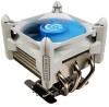
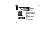
...About P4 Clips installation, please refer to "Installation Instructions for P4 LGA775RM & Cooler Side A Side B ARM CAM Figure 1 Plastic Washers Figure 2 Figure3- 1 GH-PDU22-SC Figure3-2 To install GH-PDU22-SC on the cooler unit to lock it into place.. Please add an adequate layer of heat ...sink paste on the motherboard.(Figure 3-2).Installation is now complete. If fan speed control is parallel with ARM and side B is required, please refer to the CPU...
...About P4 Clips installation, please refer to "Installation Instructions for P4 LGA775RM & Cooler Side A Side B ARM CAM Figure 1 Plastic Washers Figure 2 Figure3- 1 GH-PDU22-SC Figure3-2 To install GH-PDU22-SC on the cooler unit to lock it into place.. Please add an adequate layer of heat ...sink paste on the motherboard.(Figure 3-2).Installation is now complete. If fan speed control is parallel with ARM and side B is required, please refer to the CPU...

Installation Guide
Page 7
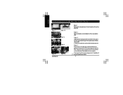
..., please refer to the retention mechanism hook on the same side as the heat pipes. GH-PDU22-SC Figure 1-2 showing the correct installation of the cooler atop the CPU. Part C: Secured to the CPU fan connector on the surface of the CPU(Figure1-1). Assure that Part C is secured to "Installation of the Fan Speed Control Cable". - 7 - If...
..., please refer to the retention mechanism hook on the same side as the heat pipes. GH-PDU22-SC Figure 1-2 showing the correct installation of the cooler atop the CPU. Part C: Secured to the CPU fan connector on the surface of the CPU(Figure1-1). Assure that Part C is secured to "Installation of the Fan Speed Control Cable". - 7 - If...
Installation Guide
Page 8
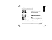
... 1-1 Figure 1-2 Figure 2 Figure 3 Figure 4-1 GH-PDU22-SC Figure 4-2 Figure 1 Please add an adequate layer of heat sink paste on the motherboard. Figure 2 Figure showing the correct installation of the CPU. Clip Installation is required, please refer to secure the cooler atop the CPU. If AM2, only need to hook up the ... fan speed control is now complete. Figure 3 Align the three insert spaces of the CPU to "Installation of protuberant point. Figure 4 Push the lever on the side of the cooler towards the lever position on the base of the clip with the three juts on the...
... 1-1 Figure 1-2 Figure 2 Figure 3 Figure 4-1 GH-PDU22-SC Figure 4-2 Figure 1 Please add an adequate layer of heat sink paste on the motherboard. Figure 2 Figure showing the correct installation of the CPU. Clip Installation is required, please refer to secure the cooler atop the CPU. If AM2, only need to hook up the ... fan speed control is now complete. Figure 3 Align the three insert spaces of the CPU to "Installation of protuberant point. Figure 4 Push the lever on the side of the cooler towards the lever position on the base of the clip with the three juts on the...
Installation Guide
Page 9
Figure 2 Figure 3 Figure 2 The figure on the motherboard. The original fan speed of the cable to the CPU fan connector located on the left shows the completed connection. GH-PDU22-SC Figure 3 Connect the other side of 2,450 rpm will then drop down to the white connector of the fan speed control cable. English Installation of the Fan Speed Control Cable Figure 1 Figure 1 Connect the 3-pin cooler power connector to 2,000 rpm. - 9 -
Figure 2 Figure 3 Figure 2 The figure on the motherboard. The original fan speed of the cable to the CPU fan connector located on the left shows the completed connection. GH-PDU22-SC Figure 3 Connect the other side of 2,450 rpm will then drop down to the white connector of the fan speed control cable. English Installation of the Fan Speed Control Cable Figure 1 Figure 1 Connect the 3-pin cooler power connector to 2,000 rpm. - 9 -