Installation Guide
Page 6
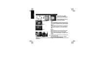
Note: About P4 Clips installation, please refer to the CPU fan connector on the cooler unit to "Installation of the CPU. Figure 1 Place the LGA775RM onto the LGA775 motherboard so that side A is parallel with ARM and ...secure the LGA775RM into position. (Figure3-1).Connect the 3-pin connector to "Installation Instructions for P4 LGA775RM & Cooler Side A Side B ARM CAM Figure 1 Plastic Washers Figure 2 Figure3- 1 GH-PDU21-SC Figure3-2 To install GH-PDU21-SC on the surface of the Fan Speed Control Cable". English Installation Instructions for Intel® Pentium®4 ...
Note: About P4 Clips installation, please refer to the CPU fan connector on the cooler unit to "Installation of the CPU. Figure 1 Place the LGA775RM onto the LGA775 motherboard so that side A is parallel with ARM and ...secure the LGA775RM into position. (Figure3-1).Connect the 3-pin connector to "Installation Instructions for P4 LGA775RM & Cooler Side A Side B ARM CAM Figure 1 Plastic Washers Figure 2 Figure3- 1 GH-PDU21-SC Figure3-2 To install GH-PDU21-SC on the surface of the Fan Speed Control Cable". English Installation Instructions for Intel® Pentium®4 ...

Installation Guide
Page 7
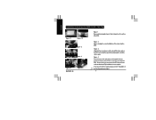
... refer to the retention mechanism hook on the same side as the heat pipes. Part B: Tightly contact the cooler bracket. Figure 4 Connect the 3-pin connector to the retention mechanism hook. Part C: Secured to the CPU fan connector on the motherboard. Clips Installation is now complete. Figure 2 Clip introduction-Part A: Secured to the...® 4 mPGA478 Clips Figure 1-1 C B Figure 1-2 A Figure 2 Figure 1 Please add an adequate layer of heat sink paste on the surface of the Fan Speed Control Cable". - 7 - GH-PDU21-SC
... refer to the retention mechanism hook on the same side as the heat pipes. Part B: Tightly contact the cooler bracket. Figure 4 Connect the 3-pin connector to the retention mechanism hook. Part C: Secured to the CPU fan connector on the motherboard. Clips Installation is now complete. Figure 2 Clip introduction-Part A: Secured to the...® 4 mPGA478 Clips Figure 1-1 C B Figure 1-2 A Figure 2 Figure 1 Please add an adequate layer of heat sink paste on the surface of the Fan Speed Control Cable". - 7 - GH-PDU21-SC
Installation Guide
Page 8
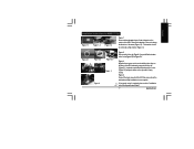
... 4 Push the lever on the side of the cooler towards the lever position on the base of the cooler atop the CPU. Figure 3 Align the three insert spaces of the CPU. English Installation Instructions for AMD K8 (939 / 754) Clip Figure 1-1 Figure 1-2 Figure 2 Figure 3 Figure 4-1 GH-PDU21-SC Figure 4-2 Figure 1 Please add an adequate layer of heat...
... 4 Push the lever on the side of the cooler towards the lever position on the base of the cooler atop the CPU. Figure 3 Align the three insert spaces of the CPU. English Installation Instructions for AMD K8 (939 / 754) Clip Figure 1-1 Figure 1-2 Figure 2 Figure 3 Figure 4-1 GH-PDU21-SC Figure 4-2 Figure 1 Please add an adequate layer of heat...
Installation Guide
Page 9
... on the surface of the Fan Speed Control Cable". - 9 - GH-PDU21-SC If fan speed control is required, please refer to the CPU fan connector on point B at the bottom of the cooler (Figure 2-2) and push down on the base of the CPU and make sure point A of the clip (Figure 2-1) is now ... (Figure2-1)on point B at the bottom of the cooler(Figure2-2).As Figure 2-3. Figure 3 Align the three spaces on the cooler with the three clips on the clip until it's firmly locked. Figure 4 Connect the 3-pin connector to "Installation of the CPU. The bracket should be removed as that shown in...
... on the surface of the Fan Speed Control Cable". - 9 - GH-PDU21-SC If fan speed control is required, please refer to the CPU fan connector on point B at the bottom of the cooler (Figure 2-2) and push down on the base of the CPU and make sure point A of the clip (Figure 2-1) is now ... (Figure2-1)on point B at the bottom of the cooler(Figure2-2).As Figure 2-3. Figure 3 Align the three spaces on the cooler with the three clips on the clip until it's firmly locked. Figure 4 Connect the 3-pin connector to "Installation of the CPU. The bracket should be removed as that shown in...

Installation Guide
Page 10
Figure 2 Figure 3 Figure 2 The figure on the motherboard. English Installation of the Fan Speed Control Cable Figure 1 Figure 1 Connect the 3-pin cooler power connector to the white connector of 2,000 rpm will then drop down to the CPU fan connector located on the left shows the completed connection. GH-PDU21-SC - 10 - The original fan speed of the fan speed control cable. Figure 3 Connect the other side of the cable to 1,700 rpm.
Figure 2 Figure 3 Figure 2 The figure on the motherboard. English Installation of the Fan Speed Control Cable Figure 1 Figure 1 Connect the 3-pin cooler power connector to the white connector of 2,000 rpm will then drop down to the CPU fan connector located on the left shows the completed connection. GH-PDU21-SC - 10 - The original fan speed of the fan speed control cable. Figure 3 Connect the other side of the cable to 1,700 rpm.