Installation Guide
Page 2
English Table of Content Checklist...3 Specification...4 Feature...4 Warranty Item...5 Precautions...5 Installation Instructions for P4 LGA775RM & Cooler 6 Installation Instructions for Intel® Pentium® 4 mPGA478 Clips 7 Installation Instructions for AMD K8 (939 / 754) Clip 8 Installation Instructions for AMD K7 Clip 9 Installation of the Fan Speed Control Cable 10 GH-PDU21-SC - 2 -
English Table of Content Checklist...3 Specification...4 Feature...4 Warranty Item...5 Precautions...5 Installation Instructions for P4 LGA775RM & Cooler 6 Installation Instructions for Intel® Pentium® 4 mPGA478 Clips 7 Installation Instructions for AMD K8 (939 / 754) Clip 8 Installation Instructions for AMD K7 Clip 9 Installation of the Fan Speed Control Cable 10 GH-PDU21-SC - 2 -
Installation Guide
Page 3
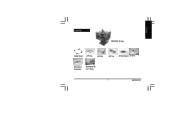
English Checklist (1)GH-PDU21 -SC Cooler (2)LGA775 RM (3) P4 clips (4) K8 clip (5) K7 clip (6) Heat sink paste (7) Screw (8) Fan Speed Control Cable (9) GH-PDU21-SC user's manual - 3 - GH-PDU21-SC
English Checklist (1)GH-PDU21 -SC Cooler (2)LGA775 RM (3) P4 clips (4) K8 clip (5) K7 clip (6) Heat sink paste (7) Screw (8) Fan Speed Control Cable (9) GH-PDU21-SC user's manual - 3 - GH-PDU21-SC

Installation Guide
Page 4
... FX55 / AMD AthlonTM XP 4000+ AMD K7 3200+ Feature y Unique and patented cooler bracket design for Intel® Pentium®4 LGA775 / mPGA 478 / AMD K8( 939/ 754 ) / K7 Platform y 4 heatpipe design y Unique fan frame design sustained by 4 artistic pillars y Brilliant Blue LEDS y Omni- No tool required GH-PDU21-SC - 4 - directional cooler design y Easy clip installation -
... FX55 / AMD AthlonTM XP 4000+ AMD K7 3200+ Feature y Unique and patented cooler bracket design for Intel® Pentium®4 LGA775 / mPGA 478 / AMD K8( 939/ 754 ) / K7 Platform y 4 heatpipe design y Unique fan frame design sustained by 4 artistic pillars y Brilliant Blue LEDS y Omni- No tool required GH-PDU21-SC - 4 - directional cooler design y Easy clip installation -
Installation Guide
Page 5
...of operation or use of alteration to original product A faulty product that is turned off and its power disconnected prior to the cooler itself as well as a result of other product components Any form of product not for reference use beyond the advised standards (eg... during installtion. - 5 - Before use, please remove the bottom protective layer of the cooler exceeding normal standards, please remove the cooler before computer transport to prevent damage to installation. Please make sure the computer is removed, torn or unreadable Due to the weight of the cooler. GH-PDU21-SC
...of operation or use of alteration to original product A faulty product that is turned off and its power disconnected prior to the cooler itself as well as a result of other product components Any form of product not for reference use beyond the advised standards (eg... during installtion. - 5 - Before use, please remove the bottom protective layer of the cooler exceeding normal standards, please remove the cooler before computer transport to prevent damage to installation. Please make sure the computer is removed, torn or unreadable Due to the weight of the cooler. GH-PDU21-SC
Installation Guide
Page 6
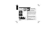
...P4 Clips installation, please refer to "Installation of the Fan Speed Control Cable". Figure 3 Gently push down on the cooler unit to the CPU fan connector on the motherboard.(Figure 3-2).Installation is parallel with CAM. Figure 2 From the underside ...- 6 - If fan speed control is required, please refer to "Installation Instructions for P4 LGA775RM & Cooler Side A Side B ARM CAM Figure 1 Plastic Washers Figure 2 Figure3- 1 GH-PDU21-SC Figure3-2 To install GH-PDU21-SC on the surface of the motherboard, use screws (4) and plastic washers (4) together to secure the LGA775RM ...
...P4 Clips installation, please refer to "Installation of the Fan Speed Control Cable". Figure 3 Gently push down on the cooler unit to the CPU fan connector on the motherboard.(Figure 3-2).Installation is parallel with CAM. Figure 2 From the underside ...- 6 - If fan speed control is required, please refer to "Installation Instructions for P4 LGA775RM & Cooler Side A Side B ARM CAM Figure 1 Plastic Washers Figure 2 Figure3- 1 GH-PDU21-SC Figure3-2 To install GH-PDU21-SC on the surface of the motherboard, use screws (4) and plastic washers (4) together to secure the LGA775RM ...

Installation Guide
Page 7
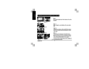
... retention mechanism hook. Figure 3-1 Figure 3-2 Figure 4 Figure 3 Secure Parts A, B, and then C of the cooler atop the CPU. Figure 1-2 showing the correct installation of the clip to "Installation of the CPU(Figure1-1). If fan speed control is now complete. GH-PDU21-SC English Installation Instructions for Intel® Pentium® 4 mPGA478 Clips Figure 1-1 C B Figure 1-2 A Figure...
... retention mechanism hook. Figure 3-1 Figure 3-2 Figure 4 Figure 3 Secure Parts A, B, and then C of the cooler atop the CPU. Figure 1-2 showing the correct installation of the clip to "Installation of the CPU(Figure1-1). If fan speed control is now complete. GH-PDU21-SC English Installation Instructions for Intel® Pentium® 4 mPGA478 Clips Figure 1-1 C B Figure 1-2 A Figure...
Installation Guide
Page 8
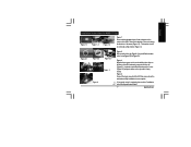
... K8 (939 / 754) Clip Figure 1-1 Figure 1-2 Figure 2 Figure 3 Figure 4-1 GH-PDU21-SC Figure 4-2 Figure 1 Please add an adequate layer of heat sink paste on the surface of the CPU to secure the cooler atop the CPU. Figure 4 Push the lever on the side of the cooler towards the lever position on the base of the... fan connector on the CPU socket and then push firmly downwards to hold the clip in space. Figure 3 Align the three insert spaces of the cooler atop the CPU.
... K8 (939 / 754) Clip Figure 1-1 Figure 1-2 Figure 2 Figure 3 Figure 4-1 GH-PDU21-SC Figure 4-2 Figure 1 Please add an adequate layer of heat sink paste on the surface of the CPU to secure the cooler atop the CPU. Figure 4 Push the lever on the side of the cooler towards the lever position on the base of the... fan connector on the CPU socket and then push firmly downwards to hold the clip in space. Figure 3 Align the three insert spaces of the cooler atop the CPU.
Installation Guide
Page 9
...GH-PDU21-SC English Installation Instructions for AMD K7 Clip Figure 1-1 A Figure 1-2 B Figure 1-3 Figure 2-1 Figure 2-2 Figure 2-3 Figure 3 Figure 4 Figure 1 Please add an adequate layer of heat sink paste on the motherboard. Figure 4 Connect the 3-pin connector to "Installation of the arrow (Figure 1-2). Figure 3 Align the three spaces on the cooler...bracket should be removed as that shown in Figure 1-3. Clip Installation is placed on point B at the bottom of the cooler (Figure 2-2) and push down on point B at the bottom of the clip (Figure2-1)on the clip until it's...
...GH-PDU21-SC English Installation Instructions for AMD K7 Clip Figure 1-1 A Figure 1-2 B Figure 1-3 Figure 2-1 Figure 2-2 Figure 2-3 Figure 3 Figure 4 Figure 1 Please add an adequate layer of heat sink paste on the motherboard. Figure 4 Connect the 3-pin connector to "Installation of the arrow (Figure 1-2). Figure 3 Align the three spaces on the cooler...bracket should be removed as that shown in Figure 1-3. Clip Installation is placed on point B at the bottom of the cooler (Figure 2-2) and push down on point B at the bottom of the clip (Figure2-1)on the clip until it's...

Installation Guide
Page 10
The original fan speed of the fan speed control cable. GH-PDU21-SC - 10 - Figure 2 Figure 3 Figure 2 The figure on the motherboard. English Installation of the Fan Speed Control Cable Figure 1 Figure 1 Connect the 3-pin cooler power connector to the white connector of 2,000 rpm will then drop down to the CPU fan connector located on the left shows the completed connection. Figure 3 Connect the other side of the cable to 1,700 rpm.
The original fan speed of the fan speed control cable. GH-PDU21-SC - 10 - Figure 2 Figure 3 Figure 2 The figure on the motherboard. English Installation of the Fan Speed Control Cable Figure 1 Figure 1 Connect the 3-pin cooler power connector to the white connector of 2,000 rpm will then drop down to the CPU fan connector located on the left shows the completed connection. Figure 3 Connect the other side of the cable to 1,700 rpm.
