
Manual
Page 2
Table of Contents TPM Configuration Procedure 3 1. Initializing the TPM Chip with the Smart TPM Utility 5 3.2. Creating a Bluetooth Cell Phone Key 19 4.3. Other Features...21 - 2 - Installing the Infineon TPM Driver 4 2.2. Configuring the Smart TPM Utility 18 4.1. Installing the Infineon TPM Driver and the Smart TPM Utility 4 2.1. Initializing the TPM chip 5 3.1. Creating a USB Key 18 4.2. Advanced Mode...8 4. Installing the Smart TPM Utility 4 3. Configuring the System BIOS 3 2. Other Bluetooth Settings 21 4.4.
Table of Contents TPM Configuration Procedure 3 1. Initializing the TPM Chip with the Smart TPM Utility 5 3.2. Creating a Bluetooth Cell Phone Key 19 4.3. Other Features...21 - 2 - Installing the Infineon TPM Driver 4 2.2. Configuring the Smart TPM Utility 18 4.1. Installing the Infineon TPM Driver and the Smart TPM Utility 4 2.1. Initializing the TPM chip 5 3.1. Creating a USB Key 18 4.2. Advanced Mode...8 4. Installing the Smart TPM Utility 4 3. Configuring the System BIOS 3 2. Other Bluetooth Settings 21 4.4.

Manual
Page 5
...to the instructions in Section 3.2) to launch the Infineon Security Platform Initialization Wizard to the Bluetooth cell phone or when plugging in the USB flash drive that the Infineon Security Platform is not yet initialized, will appear in the notification area. Double-click the icon or right...-click the Smart TPM icon and select Initialization Wizard to your Bluetooth cell phone or USB flash drive. Specify the PSD drive letter, drive label, size, and a local drive on which indicates that is automatically provided. Personal ...
...to the instructions in Section 3.2) to launch the Infineon Security Platform Initialization Wizard to the Bluetooth cell phone or when plugging in the USB flash drive that the Infineon Security Platform is not yet initialized, will appear in the notification area. Double-click the icon or right...-click the Smart TPM icon and select Initialization Wizard to your Bluetooth cell phone or USB flash drive. Specify the PSD drive letter, drive label, size, and a local drive on which indicates that is automatically provided. Personal ...

Manual
Page 7
... turn on the search and Bluetooth functions on the left will overwrite the former. 2. Step 3: Create Your Smart TPM Key 1. Then select the USB flash drive that on your cell phone. Then select the cell phone that you want to use as the portable Smart TPM user key. Create... a Bluetooth cell phone key: Select the Use Bluetooth Device check box and click Refresh to search for the USB flash drive(s) that you want to search for the Bluetooth enabled cell phone(s). Enter a passkey (8~16 digits recommended) in Passkey which will store ...
... turn on the search and Bluetooth functions on the left will overwrite the former. 2. Step 3: Create Your Smart TPM Key 1. Then select the USB flash drive that on your cell phone. Then select the cell phone that you want to use as the portable Smart TPM user key. Create... a Bluetooth cell phone key: Select the Use Bluetooth Device check box and click Refresh to search for the USB flash drive(s) that you want to search for the Bluetooth enabled cell phone(s). Enter a passkey (8~16 digits recommended) in Passkey which will store ...

Manual
Page 18
...Module) supports the industry's most advanced hardwarebased data encryption. Loss of the password(s) or the key(s) will overwrite the former. - 18 - GIGABYTE is not liable for loss of encrypted data as a result of complicated configurations. Step 2: Click Configure Smart TPM Devices to store them up the... TPM User Password and your PSD, right-click the Smart TPM icon in the USB flash drive, without the hassles of hardware damage. 4.1. Users can access data. • After creating the password(s) and key(s) associated with...
...Module) supports the industry's most advanced hardwarebased data encryption. Loss of the password(s) or the key(s) will overwrite the former. - 18 - GIGABYTE is not liable for loss of encrypted data as a result of complicated configurations. Step 2: Click Configure Smart TPM Devices to store them up the... TPM User Password and your PSD, right-click the Smart TPM icon in the USB flash drive, without the hassles of hardware damage. 4.1. Users can access data. • After creating the password(s) and key(s) associated with...

Manual
Page 19
...Infineon Security Platform Settings Tool will be able to enter the password again, go to the "Security Chip Configuration" menu in or unplugging the USB flash drive. You are able to access/close your PSD by plugging in BIOS Setup and then set earlier and click OK to "Enabled/...your Bluetooth-enabled cell phone, click Refresh to confirm, click Yes. Do not turn on the search and Bluetooth functions on the Configure USB Storages tab. Then the USB key is normal. To be locked. When prompted to let Smart TPM re-detect the device.) Before creating a Bluetooth cell phone key...
...Infineon Security Platform Settings Tool will be able to enter the password again, go to the "Security Chip Configuration" menu in or unplugging the USB flash drive. You are able to access/close your PSD by plugging in BIOS Setup and then set earlier and click OK to "Enabled/...your Bluetooth-enabled cell phone, click Refresh to confirm, click Yes. Do not turn on the search and Bluetooth functions on the Configure USB Storages tab. Then the USB key is normal. To be locked. When prompted to let Smart TPM re-detect the device.) Before creating a Bluetooth cell phone key...
Manual
Page 21
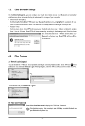
... Scan Time (sec.): Set the length of time you set . 4.3. Smart TPM searches for the key based on your portable user key is in your USB key or enable Bluetooth on the length of time Smart TPM scans your Bluetooth cell phone key and how many times Smart TPM will turn...
... Scan Time (sec.): Set the length of time you set . 4.3. Smart TPM searches for the key based on your portable user key is in your USB key or enable Bluetooth on the length of time Smart TPM scans your Bluetooth cell phone key and how many times Smart TPM will turn...

Manual
Page 6
Box Contents GA-P55-UD5 motherboard Motherboard driver disk User's Manual Quick Installation Guide One IDE cable Four SATA 3Gb/s cables I/O Shield One SATA bracket 2-Way SLI bridge connector • ... depend on the product package you obtain. The box contents are for reference only. Optional Items Floppy disk drive cable (Part No. 12CF1-1FD001-7*R) 2-port USB 2.0 bracket (Part No. 12CR1-1UB030-5*R) 2-port IEEE 1394a bracket (Part No. 12CF1-1IE008-0*R) 2-port SATA power cable (Part No. 12CF1-2SERPW-0*R) S/PDIF In cable (Part...
Box Contents GA-P55-UD5 motherboard Motherboard driver disk User's Manual Quick Installation Guide One IDE cable Four SATA 3Gb/s cables I/O Shield One SATA bracket 2-Way SLI bridge connector • ... depend on the product package you obtain. The box contents are for reference only. Optional Items Floppy disk drive cable (Part No. 12CF1-1FD001-7*R) 2-port USB 2.0 bracket (Part No. 12CR1-1UB030-5*R) 2-port IEEE 1394a bracket (Part No. 12CF1-1IE008-0*R) 2-port SATA power cable (Part No. 12CF1-2SERPW-0*R) S/PDIF In cable (Part...

Manual
Page 8
...x1 x1 2 SATA 3Gb/s JMB362 2 SATA 3Gb/s ATA-133/100/66/33 IDE Channel PCI Bus x1 GIGABYTE SATA2 TSB43AB23 3 IEEE 1394a DMI Interface 1 PCI Express x4 3 PCI Express x1 2 SATA 3Gb/s or Intel® P55 x4 x1 JMB362 Switch PCIe CLK (100 MHz) PCI Express Bus Dual BIOS 6 SATA 3Gb/s 14... USB Ports CODEC LPC Bus IT8720 Floppy COM Port PS/2 KB/Mouse TPM(Note) Surround Speaker Out Center/Subwoofer...
...x1 x1 2 SATA 3Gb/s JMB362 2 SATA 3Gb/s ATA-133/100/66/33 IDE Channel PCI Bus x1 GIGABYTE SATA2 TSB43AB23 3 IEEE 1394a DMI Interface 1 PCI Express x4 3 PCI Express x1 2 SATA 3Gb/s or Intel® P55 x4 x1 JMB362 Switch PCIe CLK (100 MHz) PCI Express Bus Dual BIOS 6 SATA 3Gb/s 14... USB Ports CODEC LPC Bus IT8720 Floppy COM Port PS/2 KB/Mouse TPM(Note) Surround Speaker Out Center/Subwoofer...

Manual
Page 10
... (eSATA/USB Combo) on the back panel sup porting up to 2 SATA 3Gb/s devices - Support for SATA RAID 0, RAID 1, and JBOD - 2 x SATA 3Gb/s connectors (GSATA2_2/GSATA2_3) supporting up to 2 SATA 3Gb/s devices - Support for SATA RAID 0, RAID 1, RAID 5, and RAID 10 GIGABYTE SATA2 chip...174; Core™ i5 series processor in the LGA1156 package (Go to GIGABYTE's website for the latest CPU support list.) L3 cache varies with CPU Chipset Intel® P55 Express Chipset Memory 4 x 1.5V DDR3 DIMM sockets supporting ...
... (eSATA/USB Combo) on the back panel sup porting up to 2 SATA 3Gb/s devices - Support for SATA RAID 0, RAID 1, and JBOD - 2 x SATA 3Gb/s connectors (GSATA2_2/GSATA2_3) supporting up to 2 SATA 3Gb/s devices - Support for SATA RAID 0, RAID 1, RAID 5, and RAID 10 GIGABYTE SATA2 chip...174; Core™ i5 series processor in the LGA1156 package (Go to GIGABYTE's website for the latest CPU support list.) L3 cache varies with CPU Chipset Intel® P55 Express Chipset Memory 4 x 1.5V DDR3 DIMM sockets supporting ...

Manual
Page 11
...1 x Chipset fan header 1 x front panel header 1 x front panel audio header 1 x CD In connector 1 x S/PDIF In header 1 x S/PDIF Out header 2 x USB 2.0/1.1 headers 1 x IEEE 1394a header 1 x serial port header 1 x clearing CMOS button 1 x power button 1 x reset button 1 x PS/2 keyboard/mouse port 1 x coaxial... S/PDIF Out connector 1 x optical S/PDIF Out connector 2 x IEEE 1394a ports 8 x USB 2.0/1.1 ports 2 x eSATA/USB Combo connectors 2 x RJ-45 ports 6 x audio jacks (Center/Subwoofer Speaker Out/Rear Speaker Out/ Side Speaker Out/Line In/Line Out...
...1 x Chipset fan header 1 x front panel header 1 x front panel audio header 1 x CD In connector 1 x S/PDIF In header 1 x S/PDIF Out header 2 x USB 2.0/1.1 headers 1 x IEEE 1394a header 1 x serial port header 1 x clearing CMOS button 1 x power button 1 x reset button 1 x PS/2 keyboard/mouse port 1 x coaxial... S/PDIF Out connector 1 x optical S/PDIF Out connector 2 x IEEE 1394a ports 8 x USB 2.0/1.1 ports 2 x eSATA/USB Combo connectors 2 x RJ-45 ports 6 x audio jacks (Center/Subwoofer Speaker Out/Rear Speaker Out/ Side Speaker Out/Line In/Line Out...

Manual
Page 21
... up to prevent an electrical short inside the cable connector. - 21 - Hardware Installation Before using this port for USB devices such as a USB keyboard/mouse, USB printer, USB flash drive and etc. Do not rock it straight out from your audio system provides an optical digital audio in ... ensure that your audio system provides a coaxial digital audio in connector. PS/2 Keyboard/Mouse Port Use this port for USB devices such as a USB keyboard/mouse, USB printer, USB flash drive and etc. Before using this port for an IEEE 1394a device. Use the port to an external audio...
... up to prevent an electrical short inside the cable connector. - 21 - Hardware Installation Before using this port for USB devices such as a USB keyboard/mouse, USB printer, USB flash drive and etc. Do not rock it straight out from your audio system provides an optical digital audio in ... ensure that your audio system provides a coaxial digital audio in connector. PS/2 Keyboard/Mouse Port Use this port for USB devices such as a USB keyboard/mouse, USB printer, USB flash drive and etc. Before using this port for an IEEE 1394a device. Use the port to an external audio...

Manual
Page 34
... unplug the power cord from the power outlet to prevent damage to the IEEE 1394a device. Pin No. Hardware Installation - 34 - For purchasing the optional USB bracket, please contact the local dealer. Definition 1 TPA+ 9 1 2 TPA- 10 2 3 GND 4 GND 5 TPB+ 6 TPB- 7 Power (12V) 8 Power (12V) 9 ...No Pin 10 GND • Do not plug the USB bracket cable into the USB header. • Prior to installing the USB bracket, be sure to turn off your computer and then attach the other end of the cable to the IEEE...
... unplug the power cord from the power outlet to prevent damage to the IEEE 1394a device. Pin No. Hardware Installation - 34 - For purchasing the optional USB bracket, please contact the local dealer. Definition 1 TPA+ 9 1 2 TPA- 10 2 3 GND 4 GND 5 TPB+ 6 TPB- 7 Power (12V) 8 Power (12V) 9 ...No Pin 10 GND • Do not plug the USB bracket cable into the USB header. • Prior to installing the USB bracket, be sure to turn off your computer and then attach the other end of the cable to the IEEE...

Manual
Page 40
... features available on the CPU, and the primary display adapter. Integrated Peripherals Use this menu to configure all peripheral devices, such as IDE, SATA, USB, integrated audio, and integrated LAN, etc. Power Management Setup Use this menu to configure the TPM function. A supervisor password allows you to save the...
... features available on the CPU, and the primary display adapter. Integrated Peripherals Use this menu to configure all peripheral devices, such as IDE, SATA, USB, integrated audio, and integrated LAN, etc. Power Management Setup Use this menu to configure the TPM function. A supervisor password allows you to save the...

Manual
Page 53
... here synchronize with the settings of the SMART QuickBoot of the hard drive and to accept. Options are: Floppy, LS120, Hard Disk, CDROM, ZIP, USB-FDD, USB-ZIP, USB-CDROM, USB-HDD, Legacy LAN, Disabled. For more information about Intel CPUs' unique features, please visit Intel's website. - 53 - Setup A password is only required for...
... here synchronize with the settings of the SMART QuickBoot of the hard drive and to accept. Options are: Floppy, LS120, Hard Disk, CDROM, ZIP, USB-FDD, USB-ZIP, USB-CDROM, USB-HDD, Legacy LAN, Disabled. For more information about Intel CPUs' unique features, please visit Intel's website. - 53 - Setup A password is only required for...

Manual
Page 55
... Peripherals CMOS Setup Utility-Copyright (C) 1984-2009 Award Software Integrated Peripherals SATA RAID/AHCI Mode SATA Port0-3 Native Mode USB Controllers USB Legacy Function USB Storage Function Azalia Codec PCI Express x4/x1 Slot Onboard H/W 1394 Onboard H/W LAN1 Onboard H/W LAN2 Green LAN }...: Exit F1: General Help F7: Optimized Defaults SATA RAID/AHCI Mode (Intel P55 Chipset) Enables or disables RAID for the SATA controllers integrated in the Intel P55 Chipset or configures the SATA controllers to AHCI mode. AHCI Configures the SATA controllers...
... Peripherals CMOS Setup Utility-Copyright (C) 1984-2009 Award Software Integrated Peripherals SATA RAID/AHCI Mode SATA Port0-3 Native Mode USB Controllers USB Legacy Function USB Storage Function Azalia Codec PCI Express x4/x1 Slot Onboard H/W 1394 Onboard H/W LAN1 Onboard H/W LAN2 Green LAN }...: Exit F1: General Help F7: Optimized Defaults SATA RAID/AHCI Mode (Intel P55 Chipset) Enables or disables RAID for the SATA controllers integrated in the Intel P55 Chipset or configures the SATA controllers to AHCI mode. AHCI Configures the SATA controllers...

Manual
Page 56
... Codec Enables or disables the onboard audio function. (Default: Auto) If you wish to install a 3rd party add-in network card instead of the USB functionalities below. Please note that cannot be disabled automatically. (Default: Disabled) BIOS Setup - 56 - Auto Sets the PCIEX4_1 slot to operate at x1... enabled, the system will turn off all of using the onboard audio, set this item to Disabled. SATA Port0-3 Native Mode (Intel P55 Chipset) Specifies the operating mode of using the onboard LAN, set this item to operate in Legacy IDE mode. Enable Native IDE mode ...
... Codec Enables or disables the onboard audio function. (Default: Auto) If you wish to install a 3rd party add-in network card instead of the USB functionalities below. Please note that cannot be disabled automatically. (Default: Disabled) BIOS Setup - 56 - Auto Sets the PCIEX4_1 slot to operate at x1... enabled, the system will turn off all of using the onboard audio, set this item to Disabled. SATA Port0-3 Native Mode (Intel P55 Chipset) Specifies the operating mode of using the onboard LAN, set this item to operate in Legacy IDE mode. Enable Native IDE mode ...

Manual
Page 67
... operating system, insert the motherboard driver disk into your mouse and select Uninstall) and restart the system. (The system will then autodetect and install the USB 2.0 driver.) - 67 - The driver Autorun screen is installing the drivers. You can install other drivers. • After the drivers are recommended to ... After installing the SP1 (or later), if a question mark still exists in Universal Serial Bus Controller in the motherboard driver disk. • For USB 2.0 driver support under the Windows XP operating system, please install the Windows XP Service Pack 1 or later.
... operating system, insert the motherboard driver disk into your mouse and select Uninstall) and restart the system. (The system will then autodetect and install the USB 2.0 driver.) - 67 - The driver Autorun screen is installing the drivers. You can install other drivers. • After the drivers are recommended to ... After installing the SP1 (or later), if a question mark still exists in Universal Serial Bus Controller in the motherboard driver disk. • For USB 2.0 driver support under the Windows XP operating system, please install the Windows XP Service Pack 1 or later.

Manual
Page 71
... data and perform restoration of system memory • VESA compatible graphics card • Windows XP with Xpress Recovery cannot be restored using Xpress Recovery2. • USB hard drives are not supported. • Hard drives in RAID/AHCI mode are different utilities. Installing Windows Vista and Partitioning the Hard Drive Step 1: Click...
... data and perform restoration of system memory • VESA compatible graphics card • Windows XP with Xpress Recovery cannot be restored using Xpress Recovery2. • USB hard drives are not supported. • Hard drives in RAID/AHCI mode are different utilities. Installing Windows Vista and Partitioning the Hard Drive Step 1: Click...

Manual
Page 74
...Flash by adding one more physical BIOS chip. Before You Begin 1. P55-UD5 F1f . . . . : BIOS Setup : XpressRecovery2 : Boot Menu : Qflash 07/09/2009-P55-7A89RG0GC-00 Because BIOS flashing is saved to a hard drive in system malfunction. GIGABYTE Q-Flash and @BIOS are easy-to-use the key during the ...) to access Q-Flash. Note: You can update the system BIOS without the need to enter Q-Flash. Motherboards that matches your floppy disk, USB flash drive, or hard drive. For the sake of your computer by either pressing the key during the POST to your motherboard model. 2. ...
...Flash by adding one more physical BIOS chip. Before You Begin 1. P55-UD5 F1f . . . . : BIOS Setup : XpressRecovery2 : Boot Menu : Qflash 07/09/2009-P55-7A89RG0GC-00 Because BIOS flashing is saved to a hard drive in system malfunction. GIGABYTE Q-Flash and @BIOS are easy-to-use the key during the ...) to access Q-Flash. Note: You can update the system BIOS without the need to enter Q-Flash. Motherboards that matches your floppy disk, USB flash drive, or hard drive. For the sake of your computer by either pressing the key during the POST to your motherboard model. 2. ...

Manual
Page 75
... update process is saved. Select the BIOS update file and press . When the message "Are you save the current BIOS file. • Q-Flash only supports USB flash drive or hard drives using FAT32/16/12 file system. • If the BIOS update file is saved to a hard drive in RAID/AHCI... process. • Do not turn off or restart the system when the system is reading/updating the BIOS. • Do not remove the floppy disk, USB flash drive, or hard drive when the system is displayed on the screen.
... update process is saved. Select the BIOS update file and press . When the message "Are you save the current BIOS file. • Q-Flash only supports USB flash drive or hard drives using FAT32/16/12 file system. • If the BIOS update file is saved to a hard drive in RAID/AHCI... process. • Do not turn off or restart the system when the system is reading/updating the BIOS. • Do not remove the floppy disk, USB flash drive, or hard drive when the system is displayed on the screen.


