
Manual
Page 1
GA-P55-UD5 LGA1156 socket motherboard for Intel® Core™ i7 processor family/ Intel® Core™ i5 processor family User's Manual Rev. 1001 12ME-P55UD5-1001R
GA-P55-UD5 LGA1156 socket motherboard for Intel® Core™ i7 processor family/ Intel® Core™ i5 processor family User's Manual Rev. 1001 12ME-P55UD5-1001R

Manual
Page 4
Table of Contents Box Contents...6 Optional Items...6 GA-P55-UD5 Motherboard Layout 7 Block Diagram...8 Chapter 1 Hardware Installation 9 1-1 Installation Precautions 9 1-2 Product Specifications 10 1-3 Installing the CPU and CPU Cooler 13 1-3-1 Installing the CPU 13 1-3-2 Installing the ...
Table of Contents Box Contents...6 Optional Items...6 GA-P55-UD5 Motherboard Layout 7 Block Diagram...8 Chapter 1 Hardware Installation 9 1-1 Installation Precautions 9 1-2 Product Specifications 10 1-3 Installing the CPU and CPU Cooler 13 1-3-1 Installing the CPU 13 1-3-2 Installing the ...

Manual
Page 5
...™ 2 79 4-5 Q-Share...81 4-6 Smart 6™ ...82 4-7 Smart TPM ...85 4-8 Teaming ...86 Chapter 5 Appendix...87 5-1 Configuring SATA Hard Drive(s 87 5-1-1 Configuring Intel P55 SATA Controllers 87 5-1-2 Configuring JMB362/GIGABYTE SATA2 SATA Controllers 95 5-1-3 Making a SATA RAID/AHCI Driver Diskette 101 5-1-4 Installing the SATA RAID/AHCI Driver and Operating System 102 5-2 Configuring Audio...
...™ 2 79 4-5 Q-Share...81 4-6 Smart 6™ ...82 4-7 Smart TPM ...85 4-8 Teaming ...86 Chapter 5 Appendix...87 5-1 Configuring SATA Hard Drive(s 87 5-1-1 Configuring Intel P55 SATA Controllers 87 5-1-2 Configuring JMB362/GIGABYTE SATA2 SATA Controllers 95 5-1-3 Making a SATA RAID/AHCI Driver Diskette 101 5-1-4 Installing the SATA RAID/AHCI Driver and Operating System 102 5-2 Configuring Audio...

Manual
Page 6
.... 12CF1-2SERPW-0*R) S/PDIF In cable (Part No. 12CR1-1SPDIN-0*R) COM port cable (Part No. 12CF1-1CM001-3*R) - 6 - The box contents are for reference only. Box Contents GA-P55-UD5 motherboard Motherboard driver disk User's Manual Quick Installation Guide One IDE cable Four SATA 3Gb/s cables I/O Shield One SATA bracket 2-Way SLI bridge connector •...
.... 12CF1-2SERPW-0*R) S/PDIF In cable (Part No. 12CR1-1SPDIN-0*R) COM port cable (Part No. 12CF1-1CM001-3*R) - 6 - The box contents are for reference only. Box Contents GA-P55-UD5 motherboard Motherboard driver disk User's Manual Quick Installation Guide One IDE cable Four SATA 3Gb/s cables I/O Shield One SATA bracket 2-Way SLI bridge connector •...

Manual
Page 7
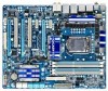
... due to a hardware limitation, the PCIEX1_1 slot can only accommodate a shorter PCI Express x1 expansion card. GA-P55-UD5 Motherboard Layout KB_USB SYS_FAN3 R_SPDIF ATX_12V_2X USB_1394_ESATA_2 USB_1394_ESATA_1 CPU_LED LGA1156 CPU_FAN PHASE LED PWR_FAN DIMM_LED IDE_LED USB_LAN2 MD1 GD1 MD2... RTL8111D PCH_FAN RTL8111D PCIEX1_2 Intel® P55 PCIEX16_1 CODEC PCI1 GA-P55-UD5 SPDIF_I CD_IN PCIEX8_1 SPDIF_O PCI2 TPM_IC(Note 2) PCI_LED PCIEX4_1 IDE DDR3_2 DDR3_1 DDR3_4 DDR3_3 ATX PE_LED SYS_FAN1 B_BIOS M_BIOS GIGABYTE SATA2 JMB362 SATA2_1 SATA2_0 SATA2_3 SATA2_2 SATA2_5...
... due to a hardware limitation, the PCIEX1_1 slot can only accommodate a shorter PCI Express x1 expansion card. GA-P55-UD5 Motherboard Layout KB_USB SYS_FAN3 R_SPDIF ATX_12V_2X USB_1394_ESATA_2 USB_1394_ESATA_1 CPU_LED LGA1156 CPU_FAN PHASE LED PWR_FAN DIMM_LED IDE_LED USB_LAN2 MD1 GD1 MD2... RTL8111D PCH_FAN RTL8111D PCIEX1_2 Intel® P55 PCIEX16_1 CODEC PCI1 GA-P55-UD5 SPDIF_I CD_IN PCIEX8_1 SPDIF_O PCI2 TPM_IC(Note 2) PCI_LED PCIEX4_1 IDE DDR3_2 DDR3_1 DDR3_4 DDR3_3 ATX PE_LED SYS_FAN1 B_BIOS M_BIOS GIGABYTE SATA2 JMB362 SATA2_1 SATA2_0 SATA2_3 SATA2_2 SATA2_5...

Manual
Page 8
... x1 2 SATA 3Gb/s JMB362 2 SATA 3Gb/s ATA-133/100/66/33 IDE Channel PCI Bus x1 GIGABYTE SATA2 TSB43AB23 3 IEEE 1394a DMI Interface 1 PCI Express x4 3 PCI Express x1 2 SATA 3Gb/s or Intel® P55 x4 x1 JMB362 Switch PCIe CLK (100 MHz) PCI Express Bus Dual BIOS 6 SATA 3Gb/s 14 USB...
... x1 2 SATA 3Gb/s JMB362 2 SATA 3Gb/s ATA-133/100/66/33 IDE Channel PCI Bus x1 GIGABYTE SATA2 TSB43AB23 3 IEEE 1394a DMI Interface 1 PCI Express x4 3 PCI Express x1 2 SATA 3Gb/s or Intel® P55 x4 x1 JMB362 Switch PCIe CLK (100 MHz) PCI Express Bus Dual BIOS 6 SATA 3Gb/s 14 USB...

Manual
Page 10
.../Intel® Core™ i5 series processor in the LGA1156 package (Go to GIGABYTE's website for the latest CPU support list.) L3 cache varies with CPU Chipset Intel® P55 Express Chipset Memory 4 x 1.5V DDR3 DIMM sockets supporting up to...MHz memory modules Support for non-ECC memory modules Support for Extreme Memory Profile (XMP) memory modules (Go to GIGABYTE's website for the latest memory support list.) Audio Realtek ALC889A codec High Definition Audio 2/4/5.1/7.1-channel ...
.../Intel® Core™ i5 series processor in the LGA1156 package (Go to GIGABYTE's website for the latest CPU support list.) L3 cache varies with CPU Chipset Intel® P55 Express Chipset Memory 4 x 1.5V DDR3 DIMM sockets supporting up to...MHz memory modules Support for non-ECC memory modules Support for Extreme Memory Profile (XMP) memory modules (Go to GIGABYTE's website for the latest memory support list.) Audio Realtek ALC889A codec High Definition Audio 2/4/5.1/7.1-channel ...

Manual
Page 29
The P55 Chipset supports RAID 0, RAID 1, RAID 5 and RAID 10. The GIGABYTE SATA2 supports RAID 0 and RAID 1. GSATA2_1 7 1 7 1 GSATA2_0 Pin No. 1 2 3 4 5 6 7 Definition GND TXP TXN GND RXN RXP GND Please connect the L-shaped end of the ..., Blue) The SATA connectors conform to SATA 3Gb/s standard and are compatible with SATA 1.5Gb/s standard. 9) SATA2_0/1/2/3/4/5 (SATA 3Gb/s Connectors, Controlled by GIGABYTE SATA2, White) The SATA connectors conform to SATA 3Gb/s standard and are compatible with SATA 1.5Gb/s standard. Refer to Chapter 5, "Configuring SATA Hard Drive(s)," ...
The P55 Chipset supports RAID 0, RAID 1, RAID 5 and RAID 10. The GIGABYTE SATA2 supports RAID 0 and RAID 1. GSATA2_1 7 1 7 1 GSATA2_0 Pin No. 1 2 3 4 5 6 7 Definition GND TXP TXN GND RXN RXP GND Please connect the L-shaped end of the ..., Blue) The SATA connectors conform to SATA 3Gb/s standard and are compatible with SATA 1.5Gb/s standard. 9) SATA2_0/1/2/3/4/5 (SATA 3Gb/s Connectors, Controlled by GIGABYTE SATA2, White) The SATA connectors conform to SATA 3Gb/s standard and are compatible with SATA 1.5Gb/s standard. Refer to Chapter 5, "Configuring SATA Hard Drive(s)," ...

Manual
Page 38
.... The system will still be used for one time only. Note: The setting in Boot Menu. Motherboard Model BIOS Version P55-UD5 F1f . . . . : BIOS Setup : XpressRecovery2 : Boot Menu : Qflash 07/09/2009-P55-7A89RG0GC-00 Function Keys Function Keys Function Keys: : POST SCREEN Press the key to show the BIOS POST screen at...
.... The system will still be used for one time only. Note: The setting in Boot Menu. Motherboard Model BIOS Version P55-UD5 F1f . . . . : BIOS Setup : XpressRecovery2 : Boot Menu : Qflash 07/09/2009-P55-7A89RG0GC-00 Function Keys Function Keys Function Keys: : POST SCREEN Press the key to show the BIOS POST screen at...

Manual
Page 55
...: Save F6: Fail-Safe Defaults ESC: Exit F1: General Help F7: Optimized Defaults SATA RAID/AHCI Mode (Intel P55 Chipset) Enables or disables RAID for the SATA controllers integrated in the Intel P55 Chipset or configures the SATA controllers to enable advanced Serial ATA features such as Native Command Queuing and hot...
...: Save F6: Fail-Safe Defaults ESC: Exit F1: General Help F7: Optimized Defaults SATA RAID/AHCI Mode (Intel P55 Chipset) Enables or disables RAID for the SATA controllers integrated in the Intel P55 Chipset or configures the SATA controllers to enable advanced Serial ATA features such as Native Command Queuing and hot...

Manual
Page 56
... of the integrated SATA controllers. USB Legacy Function Allows USB keyboard to be disabled automatically. (Default: Disabled) BIOS Setup - 56 - SATA Port0-3 Native Mode (Intel P55 Chipset) Specifies the operating mode of using the onboard audio, set this item to Disabled.
... of the integrated SATA controllers. USB Legacy Function Allows USB keyboard to be disabled automatically. (Default: Disabled) BIOS Setup - 56 - SATA Port0-3 Native Mode (Intel P55 Chipset) Specifies the operating mode of using the onboard audio, set this item to Disabled.

Manual
Page 74
... 74 - With Q-Flash you to update the system BIOS while in BIOS Setup. Restart the system. P55-UD5 F1f . . . . : BIOS Setup : XpressRecovery2 : Boot Menu : Qflash 07/09/2009-P55-7A89RG0GC-00 Because BIOS flashing is corrupted or damaged, the backup BIOS will download the latest BIOS file ...BIOS update file is @BIOS™? @BIOS allows you can access Q-Flash by adding one more physical BIOS chip. 4-2 BIOS Update Utilities GIGABYTE motherboards provide two unique BIOS update tools, Q-Flash™ and @BIOS™. What is Q-Flash™? Normally, the system works on ...
... 74 - With Q-Flash you to update the system BIOS while in BIOS Setup. Restart the system. P55-UD5 F1f . . . . : BIOS Setup : XpressRecovery2 : Boot Menu : Qflash 07/09/2009-P55-7A89RG0GC-00 Because BIOS flashing is corrupted or damaged, the backup BIOS will download the latest BIOS file ...BIOS update file is @BIOS™? @BIOS allows you can access Q-Flash by adding one more physical BIOS chip. 4-2 BIOS Update Utilities GIGABYTE motherboards provide two unique BIOS update tools, Q-Flash™ and @BIOS™. What is Q-Flash™? Normally, the system works on ...

Manual
Page 87
... one hard drive. • An empty formatted floppy disk. • Windows Vista/XP setup disk. • Motherboard driver disk. 5-1-1 Configuring Intel P55 SATA Controllers A. Appendix Configure SATA controller mode in RAID BIOS. (Note 1) D. Chapter 5 Appendix 5-1 Configuring SATA Hard Drive(s) To configure SATA hard...drive. (Note 1) Skip this motherboard, the SATA2_0, SATA2_1, SATA2_2, SATA2_3, SATA2_4 and SATA2_5 ports are supported by P55 Chipset.) Then connect the power connector from your motherboard, refer to "Chapter 1," "Hardware Installation," to AHCI or RAID mode. - 87 -...
... one hard drive. • An empty formatted floppy disk. • Windows Vista/XP setup disk. • Motherboard driver disk. 5-1-1 Configuring Intel P55 SATA Controllers A. Appendix Configure SATA controller mode in RAID BIOS. (Note 1) D. Chapter 5 Appendix 5-1 Configuring SATA Hard Drive(s) To configure SATA hard...drive. (Note 1) Skip this motherboard, the SATA2_0, SATA2_1, SATA2_2, SATA2_3, SATA2_4 and SATA2_5 ports are supported by P55 Chipset.) Then connect the power connector from your motherboard, refer to "Chapter 1," "Hardware Installation," to AHCI or RAID mode. - 87 -...

Manual
Page 89
... RAID Volume If you press + , the MAIN MENU screen will appear (Figure 3). All Rights Reserved. [ MAIN MENU ] 1. Figure 2 Step 2: After you want to enter the P55 RAID Configuration Utility. Intel(R) Matrix Storage Manager option ROM v8.9.0.1023 PCH-D wRAID5 Copyright(C) 2003-09 Intel Corporation. Reset Disks to configure a RAID array. Configuring...
... RAID Volume If you press + , the MAIN MENU screen will appear (Figure 3). All Rights Reserved. [ MAIN MENU ] 1. Figure 2 Step 2: After you want to enter the P55 RAID Configuration Utility. Intel(R) Matrix Storage Manager option ROM v8.9.0.1023 PCH-D wRAID5 Copyright(C) 2003-09 Intel Corporation. Reset Disks to configure a RAID array. Configuring...

Manual
Page 101
...is D:\). 3: At the A:\> prompt, type the following command. Press after the command: • For the Intel P55, type (Figure 1): (Note) A:\>copy d:\bootdrv\imsm\32bit\*.* • For the JMB362/GIGABYTE SATA2, type (Figure 2): (Note) A:\>copy d:\bootdrv\gsata\32bit\*.* Figure 1 In Windows mode: Figure 2 Steps...Storage driver for 64bit system for Windows 64-bit. • For the JMB362/GIGABYTE SATA2, select 3) GIGABYTE GSATA driver for 32bit system for Windows 32-bit operating system or 4) GIGABYTE GSATA driver for 64bit system for Windows 64-bit. For example, from the menu...
...is D:\). 3: At the A:\> prompt, type the following command. Press after the command: • For the Intel P55, type (Figure 1): (Note) A:\>copy d:\bootdrv\imsm\32bit\*.* • For the JMB362/GIGABYTE SATA2, type (Figure 2): (Note) A:\>copy d:\bootdrv\gsata\32bit\*.* Figure 1 In Windows mode: Figure 2 Steps...Storage driver for 64bit system for Windows 64-bit. • For the JMB362/GIGABYTE SATA2, select 3) GIGABYTE GSATA driver for 32bit system for Windows 32-bit operating system or 4) GIGABYTE GSATA driver for 64bit system for Windows 64-bit. For example, from the menu...

Manual
Page 102
.... Windows Setup Press F6 if you need to specify additional device. Windows Setup You have chosen to the previous screen. A. Figure 1 Step 2: For the Intel P55: Insert the floppy disk containing the SATA RAID/AHCI driver and press . Select the SCSI Adapter you to install a 3rd party SCSI or RAID driver...
.... Windows Setup Press F6 if you need to specify additional device. Windows Setup You have chosen to the previous screen. A. Figure 1 Step 2: For the Intel P55: Insert the floppy disk containing the SATA RAID/AHCI driver and press . Select the SCSI Adapter you to install a 3rd party SCSI or RAID driver...

Manual
Page 104
... 2: Insert the motherboard driver disk (Method A) or the floppy disk/USB flash drive that only one RAID array exists in your system.) For the Intel P55: Step 1: Restart your system and browse to the following directory: \BootDrv\iMSM\32Bit For Windows Vista 64-bit, browse to the 64Bit folder. Then use...
... 2: Insert the motherboard driver disk (Method A) or the floppy disk/USB flash drive that only one RAID array exists in your system.) For the Intel P55: Step 1: Restart your system and browse to the following directory: \BootDrv\iMSM\32Bit For Windows Vista 64-bit, browse to the 64Bit folder. Then use...

Manual
Page 108
... operating system. If you do not enable automatic rebuild on this stage, you have equal or greater capacity than the old one.) For the Intel P55: Turn off your computer. • Enabling Automatic Rebuild Step 1: When the message "Press to enter Configuration Utility" appears, press + to manually rebuild the array in...
... operating system. If you do not enable automatic rebuild on this stage, you have equal or greater capacity than the old one.) For the Intel P55: Turn off your computer. • Enabling Automatic Rebuild Step 1: When the message "Press to enter Configuration Utility" appears, press + to manually rebuild the array in...

Manual
Page 110
... data (performance). Appendix - 110 - On the RECOVERY OPTIONS menu, select Enable Only Recovery Disk to show the recovery drive in the MAIN MENU of the P55 RAID Configuration Utility. Step 3: To check the recovery status, right-click on -screen instructions to complete and exit the RAID Configuration Utility. When a dialog box...
... data (performance). Appendix - 110 - On the RECOVERY OPTIONS menu, select Enable Only Recovery Disk to show the recovery drive in the MAIN MENU of the P55 RAID Configuration Utility. Step 3: To check the recovery status, right-click on -screen instructions to complete and exit the RAID Configuration Utility. When a dialog box...
